255
Direct Device Configurations (Solar-Log 1200 and 2000)
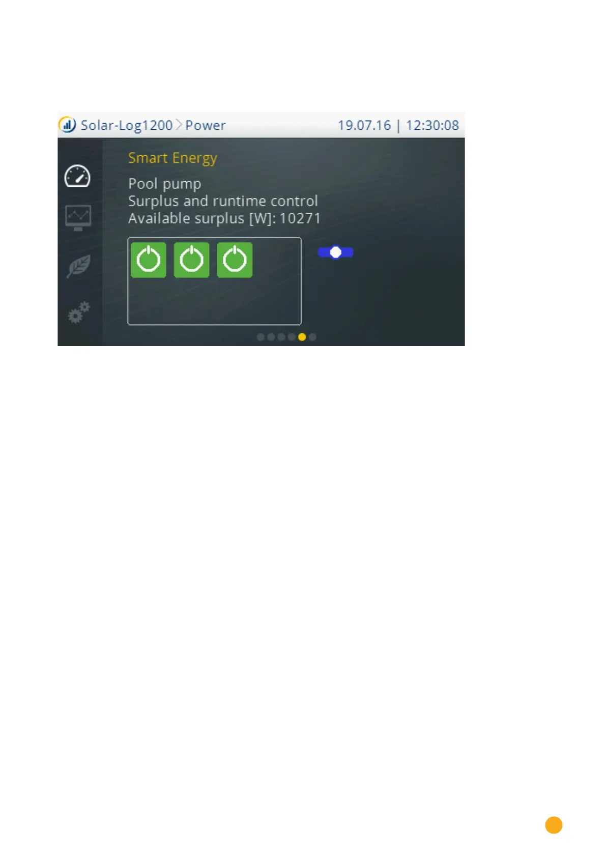
19.1.4 Start Smart Energy
Swipe in the Power menu to go to the Smart Energy section.
Fig.: Smart Energy view
The switching groups configured in the Smart Energy menu are displayed individually with the following
information is this view:
•
Switching group name
•
Logic type
•
Available surplus [W]
Below that, the state of the switching contacts within this switching group are visualized with a colored
symbol (refer to Installation Manual, chapter 23.2.1 “Switch states / Color Definition”).
There is a slide switch to the right of the switching contacts to switch the displayed switching group:
•
All of the contacts are permanently switched off (switch position “left”).
•
The contacts are switched on according to the configured automatic switching rule.
•
All of the contacts are permanently switched on (switch position “right”).
Use the arrows to display additional defined switching groups