134
Configuration Menu
Save
When using this button, the settings for the device selected as the device are saved.
Save multiple
When using this button, a selection box appears from which other devices can be added by checking them.
Save all
When using this button, all of the settings are saved for all of the detected devices.
Using the same settings for several or all of the devices is a good idea when the devices can be compared
with each other. Other than production meters, meters can be largely excluded from this section.
16.8.1 General Information on Performance Monitoring
To monitor different sized inverters, the Solar-Log™ normalized the value from every inverter to 1 kWp. The
Solar-Log™ uses the amount of generator power set in
Configuration | Devices | Configuration.
The generator power is equivalent to 100% and the value here is normalized to 1 kWp.
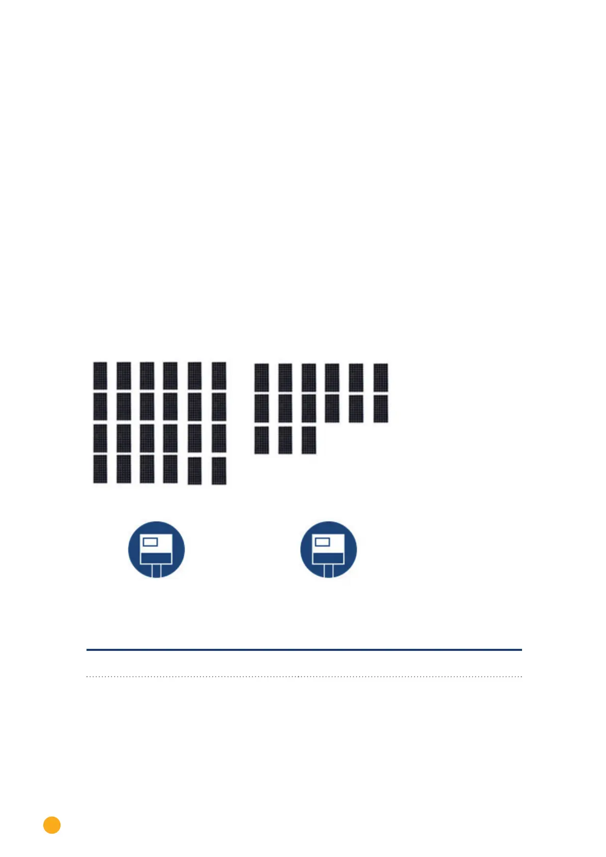
Example plant:
Fig.: Performance Monitoring: Example plant with two inverters
Inverter 1, Inverter 1 house Inverter 2, Inverter 2 house
Generator Power:
25* 220W (modules) = 5500 Wp
Generator Power:
15* 220W (modules) = 3300 Wp
Module Field 1 Module Field 1
The Solar-Log™ compares all of the inverters that are located in the same module field.
Settings for the module fields are under Configuration | Devices | Configuration.