27
Optional Connections
Combinations:
•
2x3 Phases
•
1x3 Phases + 3x1 Phase
•
6x1 Phase
•
3x2 Phases
•
2x2 Phases + 2x1 Phase
•
1x2 Phases + 4x1 Phase
The current transformers have to be connected to the Meter interface with the secondary side.
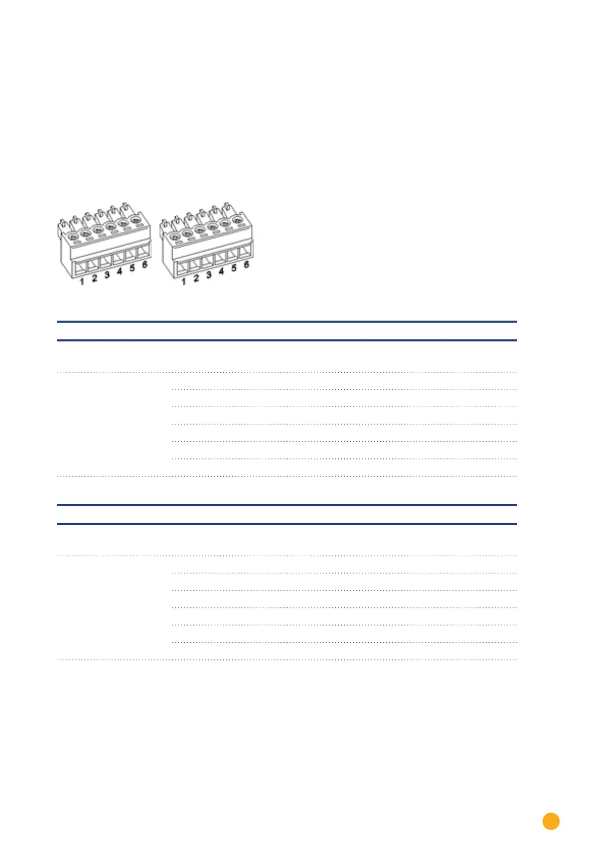
Fig.: Two 6-pin terminal block connectors for the Meter interface
Solar-Log™ Meter 1
Interface PIN Description Label
Current transformer
Meter 1 1 Current transformer/CT 1a S1/k
2 Current transformer/CT 1b S2/i
3 Current transformer/CT 2a S1/k
4 Current transformer/CT 2b S2/i
5 Current transformer/CT 3a S1/k
6 Current transformer/CT 3b S2/i
Solar-Log™ Meter 2
Interface PIN Description Label
Current transformer
Meter 2 1 Current transformer/CT 1a S1/k
2 Current transformer/CT 1b S2/i
3 Current transformer/CT 2a S1/k
4 Current transformer/CT 2b S2/i
5 Current transformer/CT 3a S1/k
6 Current transformer/CT 3b S2/i