144
Configuration Menu
16.10.3 Configuring switching groups
Use this symbol to configure the switching group. The following window appears after clicking on the
symbol:
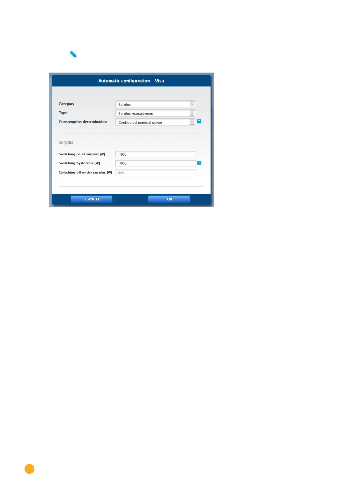
Fig.: Control logic conguration window
The configuration is divided into two section. The top section contains the following boxes:
•
Category
•
Type and
•
Consumption determination. If the Consumption meter option is selected for the Consumption
determination, an additional selection box is displayed with all of the available (sub) consumption
meters. For the temperature profiles, an additional selection box is displayed with all of the availab
-
le temperature sensors.
The bottom section is automatically determined by the selected category.
16.10.4 Control Logics Definition - Operating Mode Appliances
Various control logics can be defined with the input boxes. (See the Smart Energy Manual for more details
– available for download from our website –
The individual boxes can be combined differently, depending on the control is used.
The following rules can be selected from the Category box:
•
Surplus
•
Production
•
Consumption
•
Device-specific
•
Other
Depending on the rule, different types can be set.