105
Configuration Menu
Section Defining the Solar-Log™ Meter (only Solar-Log™ Meter)
With this model version, an extra tab Meter is displayed in the Configuration | Devices | Definition menu.
The following setting options are available in this section:
•
Input definition
•
Reference voltage
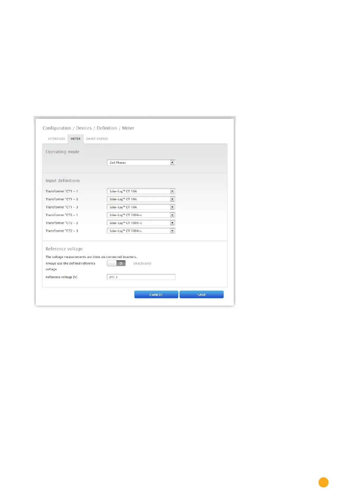
The Operating Mode section describes the setting for the various operating modes of the Solar-Log™
Meter and is to be selected in the Device Definition before Device Detection. (See figure „Operating mode
Solar-Log™ Meter)“
Fig.: Device denition for the Solar-Log™ Meter
Input definition section
•
The following CTs are available:
Solar-Log™ CT 16A
Solar-Log™ CT 100A - C
Solar-Log™ CT 100A - o
user-defined
•
The settings for the Solar-Log™ CTs have been pre-defined for the current ratio.
•
When using other CTs, select user-defined.
An additional input box appears for the current ratio of the installed CT.
The current ratio is calculated with the ratio between primary and secondary current
Example
200A of primary current results into 200mA of secondary current with a user-defined current transfor-
mer.
There is then a the current ratio of 1000 (200A/0.2A) Enter this value (1000)
in the field Current Ratio.