107
Configuration Menu
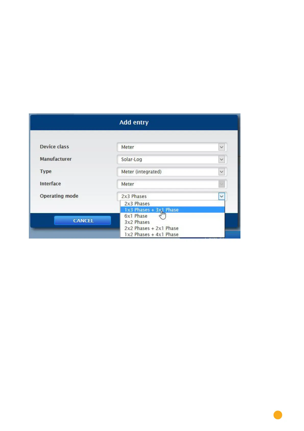
Operating mode with the Solar-Log™ Meter in connection with the interface assignment:
•
Select the desired Operating mode before the device detection in the Device Definition menu.
The listed operating modes refer to the different possible measuring combinations.
•
2x3 phases stand for the recording of two 3-phase appliances. Here the six current transformers
are combined together as two meters.
•
1x3 and 3x1 phases stand for the recording of one 3-phase appliance and three 1-phase appliances.
Here the six current transformers are combined together as four meters.
•
6x1 phase stands for the recording of six single-phase appliances. Six meters are displayed in this
mode.
•
The other modes can be used for other measuring combinations.
Fig.: Solar-Log™ Meter Operating Mode