Removing
– Select the pallet according to the size of the
fork arms.
– Position the pallet to the left or right of the
fork carriage.
– Raise the fork carriage until the lower edges
of the fork arms are approx. 3 cm higher
than the height of the pallet.
– Actuate the parking brake and make sure it
is applied securely.
– Turn the switch key to the left and pull it out.
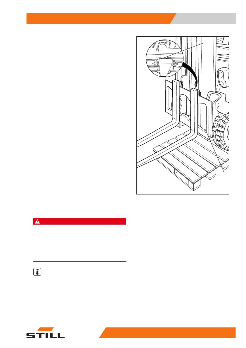
– Undo the locking screw (2) on the right or
left.
– Pull the locking lever (1) upwards and push
the fork arms outwards onto the pallet.
Installing
– Position the fork arms on a pallet to the left
or right of the fork carriage.
– Push the fork arms onto the fork carriage
from the outside towards the centre.
– Pull the locking lever (1) upwards and push
the fork arms into the required position. En-
sure that the locking lever snaps into place.
– Fit and tighten the locking screw (2).
DANGER
There is a risk of fatal injury from a falling load or
fork!
It is not permitted to drive or to transport loads with-
out the locking screw in place.
– Tighten the locking screw (2) each time a fork is
changed.
NOTE
If the truck is equipped with the "load meas-
urement" comfort feature (variant), a "zero ad-
justment of the load measurement" must al-
ways be performed after the fork arms have
been changed. Otherwise, correct load meas-
urement cannot be guaranteed.
2
1
6219_003-113
Operation
4
Lifting
24956368011531 EN - 01/2021 - 05