7B-68 Air Conditioning System: Automatic Type
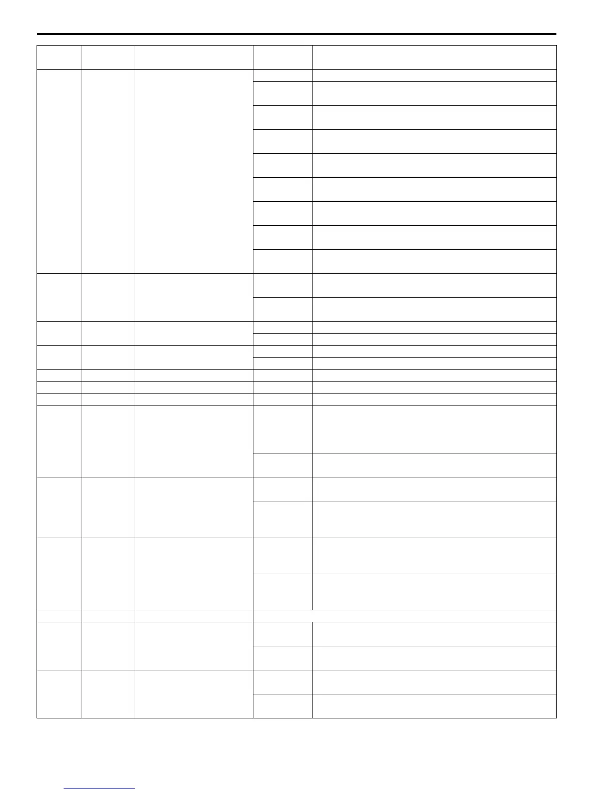
G51-8 BLU/RED
Blower motor control
voltage feedback
10 – 14 V Ignition switch turned ON, blower speed selector OFF
About 8.5 V
Ignition switch turned ON, blower speed selector 1st
position
About 6.5 V
Ignition switch turned ON, blower speed selector 2nd
position
About 5.5 V
Ignition switch turned ON, blower speed selector 3rd
position
About 4.0 V
Ignition switch turned ON, blower speed selector 4th
position
About 3.0 V
Ignition switch turned ON, blower speed selector 5th
position
About 2.0 V
Ignition switch turned ON, blower speed selector 6th
position
About 1.0 V
Ignition switch turned ON, blower speed selector 7th
position
Below 1.0 V
Ignition switch turned ON, blower speed selector HIGH
position
G51-9 GRY Blower motor controller
0 – 1 V
Ignition switch turned ON, blower speed selector OFF
position
2 – 3 V
Ignition switch turned ON, blower speed selector
between 1st and HIGH position
G51-10 BLK/RED Rear defogger indicator
0 – 1 V Ignition switch turned ON, rear defogger switch OFF
10 – 14 V Ignition switch turned ON, rear defogger switch ON
G51-11 RED/YEL Illumination switch
0 – 1 V Ignition switch turned ON, lighting switch OFF position
10 – 14 V Ignition switch turned ON, lighting switch ON position
G51-12 BLK/YEL Illumination ground 0 – 1 V Full-time
G51-13 — — — —
G51-14 — — — —
G51-15 RED
Air intake actuator
(RECIRCULATION AIR)
0 – 1 V
Ignition switch turned ON, air intake selector is
recirculation air mode or air intake actuator is working
in operation to recirculation air position or fresh air
position.
10 – 14 V
Ignition switch turned ON, air intake selector is fresh
air mode (air intake actuator fresh air position).
G51-16 GRN/RED
Air intake actuator
(MIX AIR)
10 – 14 V
Ignition switch turned ON, air intake actuator is
recirculation air or fresh air position.
0 – 1 V
Ignition switch turned ON, air intake actuator is mix air
position or air intake actuator is working in operation to
recirculation air position or fresh air position.
G51-17 GRN
Air intake actuator
(FRESH AIR)
0 – 1 V
Ignition switch turned ON, air intake selector is fresh
air mode or air intake actuator is working in operation
to recirculation air position or fresh air position.
10 – 14 V
Ignition switch turned ON, air intake selector is
recirculation air mode (air intake actuator recirculation
air position).
G51-18 GRN/WHT A/C switch signal Refer to “Inspection of BCM and its Circuits in Section 10B”
G51-19 BLU/WHT
Electric load signal for
blower motor
10 – 14 V
Ignition switch turned ON, blower speed selector OFF
or between 1st and 5th position
0 – 2 V
Ignition switch turned ON, blower speed selector
between 6th and HIGH position
G51-20 BRN Rear defogger switch
0 – 1 V
Ignition switch turned ON, rear defogger switch ON
(rear defogger switch is kept in push) position
4 – 6 V
Ignition switch turned ON, rear defogger switch OFF
position
Terminal Wire Color Circuit
Normal
Voltage
Condition
 Loading...


