1A-58 Engine General Information and Diagnosis:
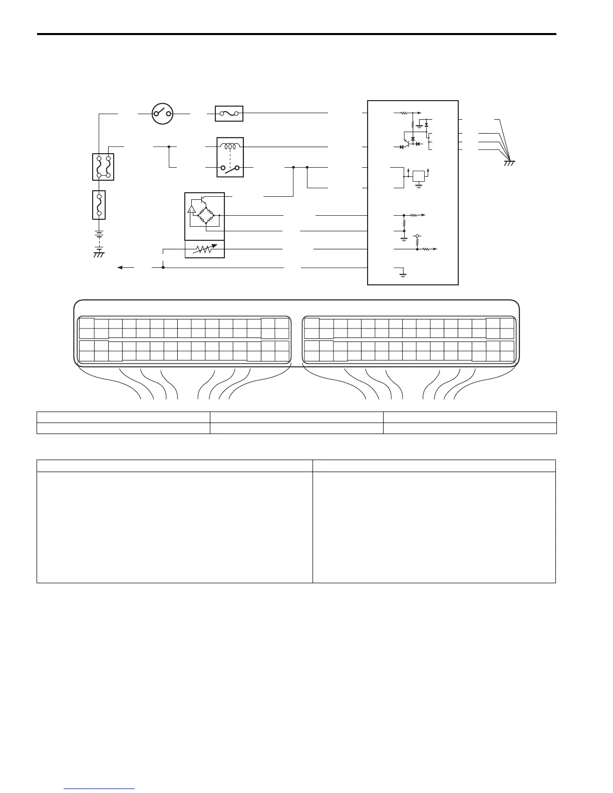
DTC P0101: Mass or Volume Air Flow Circuit Range / Performance
S7RS0B1104017
Wiring Diagram
DTC Detecting Condition and Trouble Area
E23 C37
34
1819
5671011
1720
47 46495051
2122
52
1625
9
24
14
29
5557 54 53
59
60 58
2
262728
15
30
56 48
32 31343536374042 39 38
44
45 43 41 33
11213
23
834
1819
5671011
1720
47 46495051
2122
52
1625
9
24
14
29
5557 54 53
59
60 58
2
262728
15
30
56 48
32 31343536374042 39 38
44
45 43 41 33
11213
23
8
BLK/WHT
BLK/RED
BLK/RED
WHT
BLK/YEL BLK/YEL
BLK/YEL
GRN
BRN/WHT
12V
5V
5V
2
3
4
E23-29
E23-60
E23-1
E23-16
BLK/ORN
BLK
BLK
BLK/RED
BLK/YEL
GRY/BLU
ORN
1
BLK/RED
5
E23-31
BLK
ORN
GRY
GRN/BLK
C37-58
C37-15
C37-30
C37-26
C37-27
C37-25
C37-55
I6RS0C110014-01
1. MAF and IAT sensor 3. Main relay 5. To other sensors
2. Ignition switch 4. ECM
DTC detecting condition Trouble area
• MAF volume is greater than 20 g/sec even if engine
revolution is less than 900 rpm and intake manifold
pressure is less than 40 kPa (5.80 psi) with TP less than
1.5°.
• MAF volume is lower than 10 g/sec even if engine
revolution is more than 2500 rpm and intake manifold
pressure is more than 60 kPa (8.70 psi) with TP more than
12°.
(2 driving cycle detection logic)
• Air intake system (clog or leakage)
• MAF sensor circuit
•MAF sensor
• TP sensor and/or its circuit
• MAP sensor and/or its circuit
•ECM
 Loading...


