Immobilizer Control System: 10C-4
Schematic and Routing Diagram
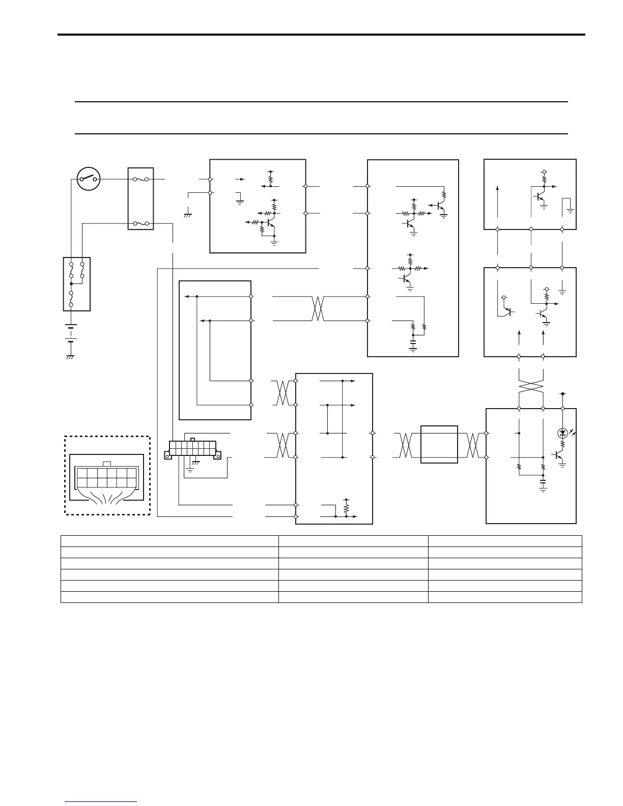
Immobilizer Control System Wiring Circuit Diagram
S7RS0BA302001
NOTE
For more details about power supply and ground circuits for ECM, BCM, keyless start control module,
ABS control module and combination meter, refer to “System Circuit Diagram in Section 9A”.
BLK/WHT
BLK/ORN
12V
G24-1
G24-2
12V
5V
12V
12V
YEL/RED
YEL/BLK
G24-4
G24-3
12V
5V
BRN
BRN/YEL
BLK/YEL
1
2
2
2
2
34
2
6712
11
9
14
12
3
4
G24
[A]
5
6
REDWHT
G42-20 G42-29 G42-30
G04-3 G04-7 G04-8
WHT/RED
5V
5V
5
G28-9 G28-7
G42-18 G42-19
E23-13
E23-28
IG1
PPL/WHT
10
PPL/WHT
PPL/WHT
E23-5
RED
WHT
**E85-46
E23-18
E23-3
RED
WHT
E46-1
E46-2
WHT
RED
G37-2
G37-4
WHT/BLK
RED/BLK
G37-1
G37-3
12V
E46-9
G37-5
13
8
**E85-42
**E85-13
**E85-44
G28-10
G28-8
*E03-8
*E03-10
*E03-12
*E03-6
I7RS0BA30001-01
[A]: Immobilizer control module connector (harness side view) 6. Immobilizer control module (ICM) 12. Steering lock unit
1. Battery 7. ECM 13. ABS/ESP® control module
2. Fuse 8. BCM 14. CAN junction connector (ESP® model)
3. Ignition switch 9. Combination meter *: ABS model
4. Junction block assembly 10. Immobilizer indicator lamp **: ESP® model
5. Data link connector (DLC) 11. Keyless start control module
 Loading...


