Air Bag System: 8B-13
Scan Tool Data
S7RS0B8204006
Data list of SDM
Definition
Back Up Volt (V)
This parameter indicates the capacity of the backup
condenser installed to maintain the ignition current (as
much as possible) even when the power supply to SDM
that ignites the inflator is shut off.
Battery Voltage (V)
Battery voltage is an analog input signal read by SDM.
System ID (4ch/8ch)
This parameter indicates the number of initiator circuits.
Driv A/B Ini Res (Driver air bag initiator resistance)
(ohm)
This parameter indicates the resistance of the driver air
bag initiator circuit.
Pass A/B Ini Res (Passenger air bag initiator
resistance) (ohm)
This parameter indicates the resistance of the passenger
air bag initiator circuit.
Driv Preten Ini Res (Driver pretensioner initiator
resistance) (ohm)
This parameter indicates the resistance of the driver seat
belt pretensioner initiator circuit.
Pass Preten Ini Res (Passenger pretensioner
initiator resistance) (ohm)
This parameter indicates the resistance of the passenger
seat belt pretensioner initiator circuit.
Driv Sidebag Ini Res (Driver side-air bag initiator
resistance) (ohm)
This parameter indicates the resistance of the driver
side-air bag initiator circuit.
Pass Sidebag Ini Res (Passenger side-air bag
initiator resistance) (ohm)
This parameter indicates the resistance of the
Passenger side-air bag initiator circuit.
Driv curtain Ini Res (Driver side curtain-air bag
initiator resistance) (ohm)
This parameter indicates the resistance of the driver side
curtain-air bag initiator circuit.
Pass curtain Ini Res (Passenger side curtain-air bag
initiator resistance) (ohm)
This parameter indicates the resistance of the passenger
side curtain-air bag initiator circuit.
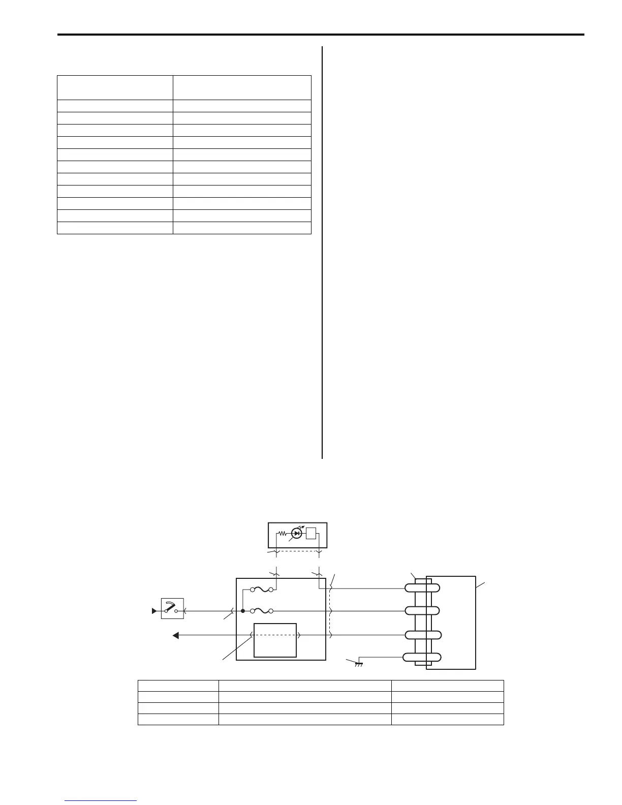
“AIR BAG” Warning Right Comes ON Steady
S7RS0B8204007
Wiring Diagram
Normal Condition /
Reference Value
) Battery voltage 10 – 14 V
) Back up volt 27.0 – 33.0 V
) System ID 4ch or 8ch
) Driv A/B Ini Res 2.1 – 3.8 ohm
) Pass A/B Ini Res 1.8 – 2.8 ohm
) Driv Preten Ini Res 1.8 – 2.9 ohm
) Pass Preten Ini Res 1.8 – 2.9 ohm
) Driv Sidebag Ini Res 1.8 – 2.6 ohm
) Pass Sidebag Ini Res 1.8 – 2.6 ohm
) Driv curtain Ini Res 1.8 – 2.8 ohm
) Pass curtain Ini Res 1.8 – 2.8 ohm
1
2
GRN
11
BLK
L29-27
L29-2
L29-28
WL
E1
IG
L29-32
ST
10
8
“L29”
RED
PPL/WHT
7
3
4
“L04”
“G34”
“G33”
“G28”
“G32”
5
6
“G32”
YEL/BLK
YEL/BLK
RED/BLK
9
I7RS0B820002-02
1. From main fuse 5. “AIR BAG” warning right in combination meter 9. To DLC
2. Ignition switch 6. Lamp driver 10. SDM
3. “METER” fuse 7. Junction block assembly 11. Ground for air bag system
4. “A/BAG” fuse 8. BCM
 Loading...


