Air Bag System: 8B-67
NOTE
Upon completion of inspection and repair work, perform the following items.
• Reconnect all air bag system components, ensure all components are properly mounted.
• Clear DTCs referring to “DTC Clearance”, if any.
• Repeat “Air Bag Diagnostic System Check” to confirm that the trouble has been corrected.
DTC B1062 / B1066: Driver / Passenger Side-Air Bag Initiator Circuit Resistance Low
S7RS0B8204031
Wiring Diagram
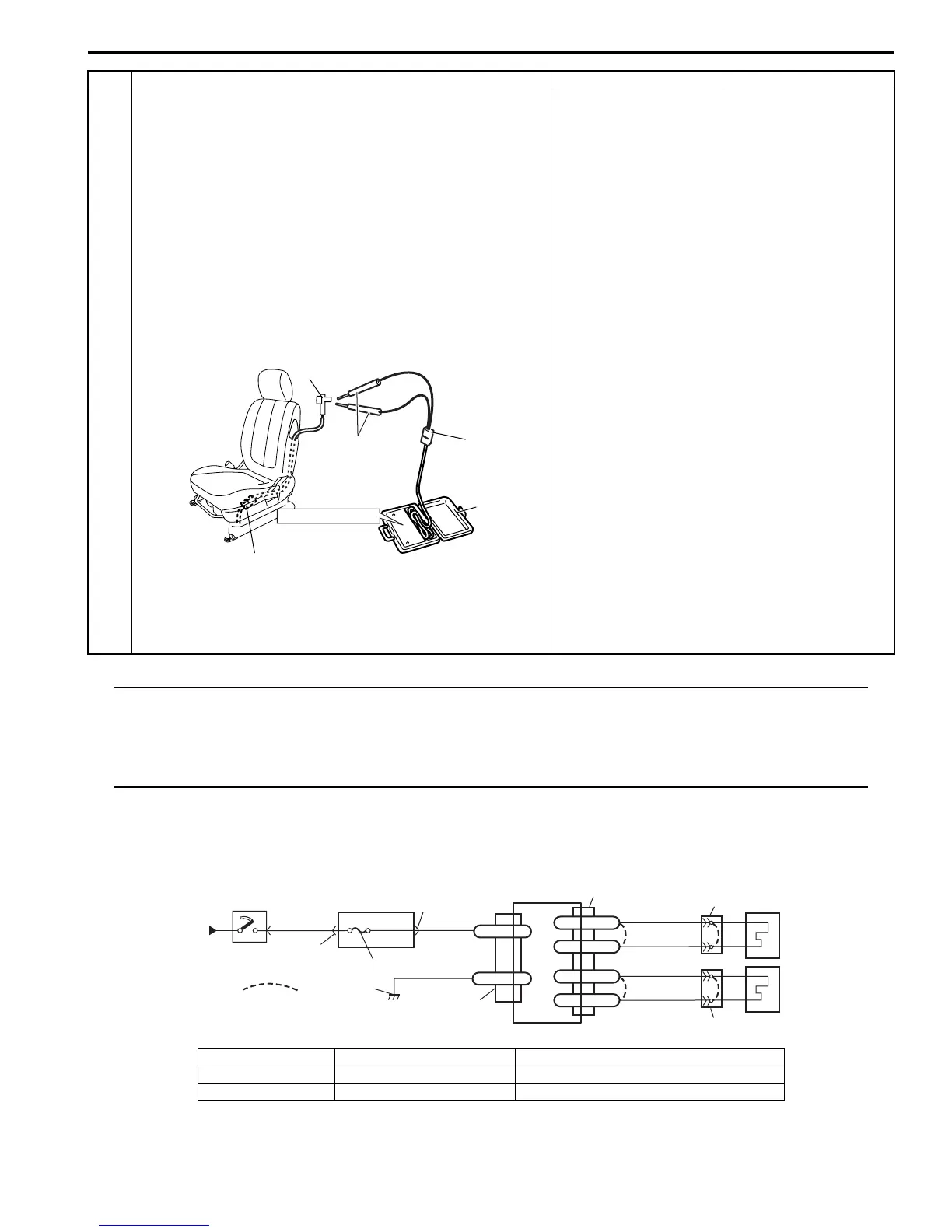
3 1) With ignition switch OFF, disconnect special tools (B)
and (C) then reconnect connector “L25” or “L30”.
2) Disconnect side-air bag (inflator) module connector (1)
from side-air bag (inflator) module.
3) Check proper connection to side-air bag (inflator)
module at terminal in connector.
4) If OK, then connect special tools (A), (B) and (C) to side-
air bag (inflator) connector.
Special tool
(A): 09932–76010
(B): 09932–75010
(C): 09932–78310
5) Check SDM DTC.
With ignition switch ON, is DTC B1061 or B1065 still
indicated?
DTC B1061: Repair
high resistance or open
in “GRY/RED” or “GRY”
wire circuit in seat
harness.
DTC B1065: Repair
high resistance or open
in “BRN/WHT” or “BRN”
wire circuit in seat
harness.
Replace side-air bag
(inflator) module
referring to “Side-Air
Bag (Inflator) Module
Removal and
Installation”.
Step Action Yes No
1
“L25”, “L30”
STEERING WHEEL
(B)
(C)
(A)
I4RS0A820034-01
1
2
3
GRN
RED
8
BLK
L29-27
L29-28
IG
E1
4
“L29”
“L04”
“G32”
“L29”
L29-12
DS+
L29-11
DS-
GRY
GRY/RED
5
6
“L25”
L29-13
PS+
L29-14
PS-
BRN
BRN/WHT
7
“L30”
[A]
I7RS0A820020-04
[A]: Shorting bar 3. “A/BAG” fuse 6. Driver side-air bag (inflator) module
1. From main fuse 4. Junction block assembly 7. Passenger side-air bag (inflator) module
2. Ignition switch 5. SDM 8. Ground for air bag system
 Loading...


