Charging System: 1J-9
Generator Unit Components
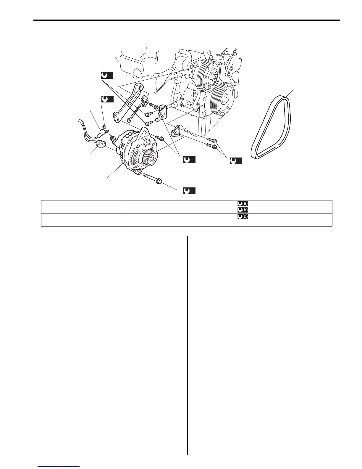
S7RS0B1A06005
Generator Dismounting and Remounting
S7RS0B1A06006
Dismounting
1) Disconnect negative (–) cable at battery.
2) Remove right side drive shaft referring to “Front
Drive Shaft Assembly Removal and Installation in
Section 3A”.
3) Disconnect generator lead wire (“B” terminal wire)
and coupler from generator.
4) Remove generator belt. Refer to “Water Pump /
Generator Drive Belt Removal and Installation”.
5) Remove generator bracket bolts and generator pivot
bolt.
6) Remove generator.
Remounting
Reverse dismounting procedure for remounting noting
the followings.
• Tighten each bolt and nut to specified torque referring
to “Generator Unit Components”.
• Adjust belt tension referring to “Water Pump /
Generator Drive Belt Tension Inspection and
Adjustment”.
(a)
(b)
(c)
1
2
8
3
7
5
4
9
6
(c)
(c)
I6RS0C1A0003-02
1. “B” terminal nut 5. Generator pivot bolt : 5 N⋅m (0.5 kgf-m, 3.5 lb-ft)
2. “B” terminal wire 6. Generator belt : 50 N⋅m (5.0 kgf-m, 36.0 lb-ft)
3. Connector 7. Generator : 25 N⋅m (2.5 kgf-m, 18.5 lb-ft)
4. Generator adjusting bolt 8. Generator bracket bolt
 Loading...


