Security and Locks: 9F-9
Power Door Lock Actuator Inspection
S7RS0B9606006
1) Remove door trim from door panel.
For front door, refer to Step 1) to 3) of “Front Door
Glass Removal and Installation in Section 9E”.
For rear door, refer to Step 1) to 3) of “Rear Door
Glass Removal and Installation in Section 9E”.
For rear end door, refer to Step 1) of “Rear End Door
Assembly Removal and Installation in Section 9J”.
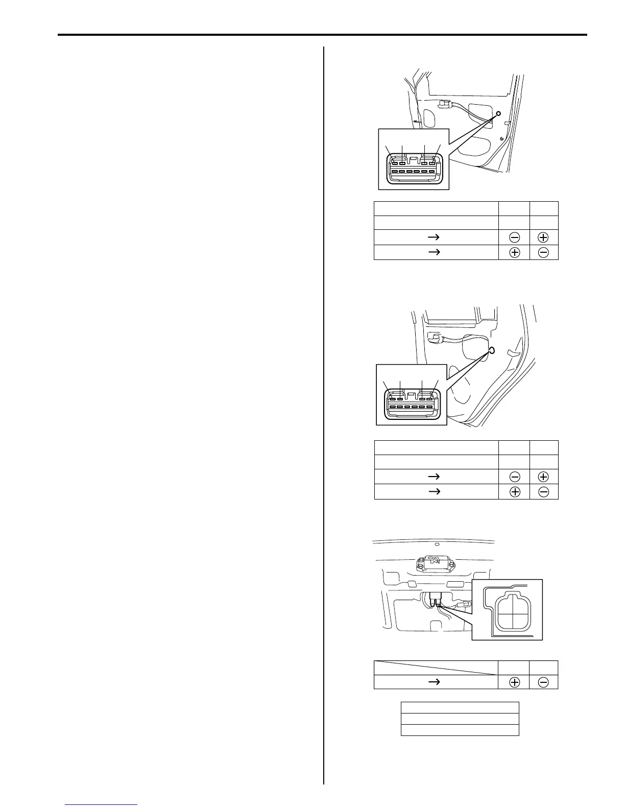
2) Disconnect power door lock actuator coupler.
3) Connect battery positive (+) and negative (–)
terminals to the door lock actuator terminals (a, b, c,
d) as shown in figure.
If it does not operate as specified in the following
table, replace door lock assembly.
[A]: Front door
[B]: Rear door
[C]: Rear end door
Unlock Lock
Lock Unlock
Right side switch terminals
Left side switch terminals
ac
db
ab cd
[A]
Unlock Lock
Lock Unlock
Right side switch terminals
Left side switch terminals
a
c
d
b
ab cd
[B]
ab
Lock Unlock
a
b
[C]
I4RS0A960011-02
 Loading...


