4F-56 Electronic Stability Program:
ESP® Hydraulic Unit / Control Module Assembly Removal and Installation
S7RS0B4606037
CAUTION
!
Never disassemble ESP® hydraulic unit / control module assembly loosen blind plug or remove motor.
Performing any of these prohibited services will affect original performance of ESP® hydraulic unit /
control module assembly.
Removal
CAUTION
!
• Do not give an impact to hydraulic unit.
• Use care not to allow dust to enter
hydraulic unit.
• Do not place hydraulic unit on its side or
upside down. Handling it in inappropriate
way will affect its original performance.
1) Disconnect negative (–) cable from battery.
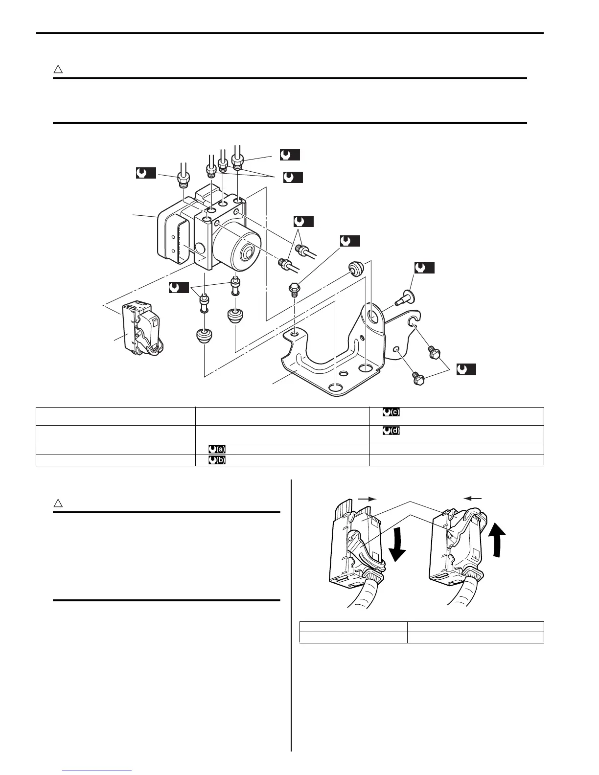
2) Disconnect ESP® control module connector (1) as
shown in figure.
3
1
(c)
2
(b)
(a)
4
(a)
4
5
6
(b)
5
(c)
6
(d)
(d)
4
4
I7RS0B460012-01
1. ESP® hydraulic unit / control module
assembly
5. ESP® hydraulic unit / control module
assembly bolt
: 25 N⋅m (2.5 kgf-m, 18.0 lb-ft)
2. Bracket 6. ESP® hydraulic unit / control module
assembly bracket bolt
: 19 N⋅m (1.9 kgf-m, 13.5 lb-ft)
3. ESP® control module connector : 16 N⋅m (1.6 kgf-m, 11.5 lb-ft)
4. Brake pipe flare nut : 9 N⋅m (0.9 kgf-m, 6.5 lb-ft)
[A]: Disconnect C: Pull down to disconnect
[B]: Connect D: Pull up to connect
2
1
C
D
[A]
[B]
I4RH01450001-01
 Loading...


