Air Conditioning System: Automatic Type 7B-71
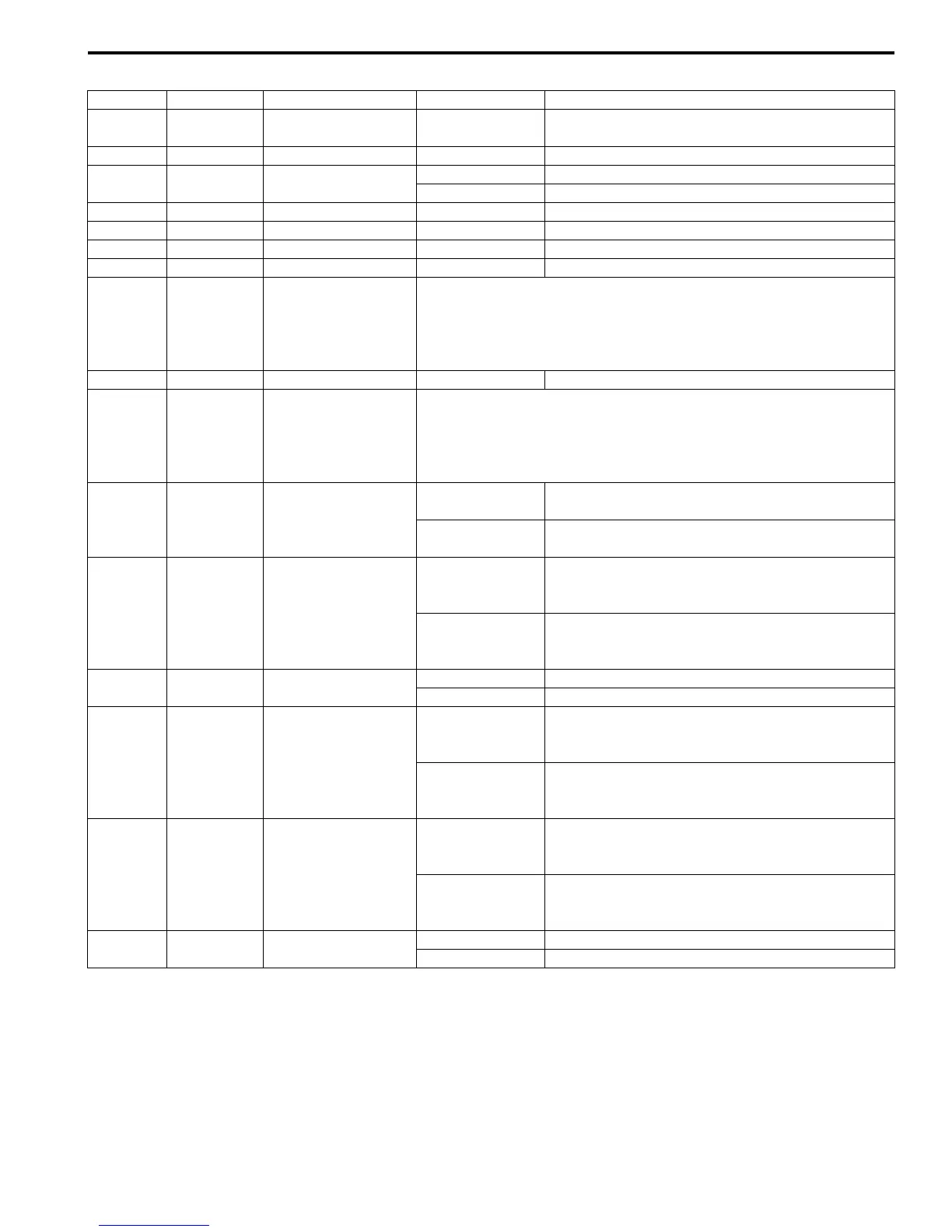
ECM Voltage Values Table for Relation of A/C Control
Repair Instructions
Operation Procedure for Refrigerant Charge
S7RS0B7226001
Refer to “Operation Procedure for Refrigerant Charge”.
Terminal Wire Color Circuit Normal Value Condition
C37-14 GRY/RED
Output of 5 V power
source
4.5 – 5.5 V Ignition switch turned ON
C37-15 BLK Ground for ECM Below 0.3 V Ignition switch turned ON
C37-24 LT GRN
Engine coolant temp.
(ETC) sensor signal
3.3 – 3.8 V Ignition switch turned ON, ECT at 0 °C (32 °F)
1.38 – 1.72 V Ignition switch turned ON, ECT at 50 °C (122 °F)
C37-30 BLK Ground for ECM Below 0.3 V Ignition switch turned ON
C37-55 ORN Ground for sensors Below 0.3 V Ignition switch turned ON
C37-58 BLK/ORN Ground for ECM Below 0.3 V Ignition switch turned ON
E23-1 BLK/RED Main power supply 10 – 14 V Ignition switch turned ON
E23-3 RED
CAN (high)
communication line
(active high signal)
for BCM and
combination meter
Refer to “DTC P2101: Throttle Actuator Control Motor Circuit Range /
Performance in Section 1A”
E23-16 BLK/RED Main power supply 10 – 14 V Ignition switch turned ON
E23-18 WHT
CAN (low)
communication line
(active low signal) for
BCM and
combination meter
Refer to “DTC P2101: Throttle Actuator Control Motor Circuit Range /
Performance in Section 1A”
E23-19 BLU/WHT
Electric load signal
for blower motor
10 – 14 V
Ignition switch turned ON, blower speed selector
OFF or between 1st and 5th position
0 – 1 V
Ignition switch turned ON, blower speed selector
between 6th and HIGH position
E23-46 LT GRN
Radiator fan relay
No.1 output
10 – 14 V
Ignition switch turned ON, engine coolant temp.:
below 95 °C (203 °F), or A/C refrigerant pressure:
below 600 kPa (87 psi).
0 – 2 V
Ignition switch turned ON, engine coolant temp.:
97.5 °C (207.5 °F) or higher, or A/C refrigerant
pressure: 1100 kPa (159.5 psi) or higher.
E23-47 GRY
A/C compressor relay
output
10 – 14 V Engine running, A/C request signal high input
0 – 1 V Engine running, A/C request signal low input
E23-48 GRN
Radiator fan relay
No.2 and No.3 output
10 – 14 V
Ignition switch turned ON, engine coolant temp.:
below 100 °C (212 °F), or A/C refrigerant
pressure: below 1200 kPa (174 psi).
0 – 2 V
Ignition switch turned ON, engine coolant temp.:
102.5 °C (216.5 °F) or higher, or A/C refrigerant
pressure: 1500 kPa (217.5 psi) or higher.
E23-55 RED
A/C refrigerant
pressure sensor
signal
1.46 – 1.71 V
Engine running, A/C refrigerant pressure at 0.8
MPa (8.0 kg/cm
2
) (A/C refrigerant pressure
measured by manifold gauge)
2.55 – 2.80 V
Engine running, A/C refrigerant pressure at 1.6
MPa (16.0 kg/cm
2
) (A/C refrigerant pressure
measured by manifold gauge)
E23-60 BRN/WHT
Main power supply
relay output
10 – 14 V Ignition switch turned OFF
0 – 2 V Ignition switch turned ON
 Loading...


