Electronic Stability Program: 4F-21
Stability control (ACTIVE, INACTIVE): This indicates
stability control in activation / deactivation.
TCS control (brake) (ACTIVE, INACTIVE): This
indicates brake function of TCS in activation /
deactivation.
TCS control (engine) (ACTIVE, INACTIVE): This
indicates torque control of TCS in activation /
deactivation.
ESP® off state (cont) (ESP® ON, ESP® OFF): State
of ESP® OFF switch.
Steering angle Sen (Neutral, NON newtral): This
indicates steering wheel angle measured by steering
angle sensor is in straight-ahead or not.
Visual Inspection
S7RS0B4604059
Check the following parts and systems visually.
ESP® Warning Lamp Does Not Come ON at Ignition Switch ON
S7RS0B4604008
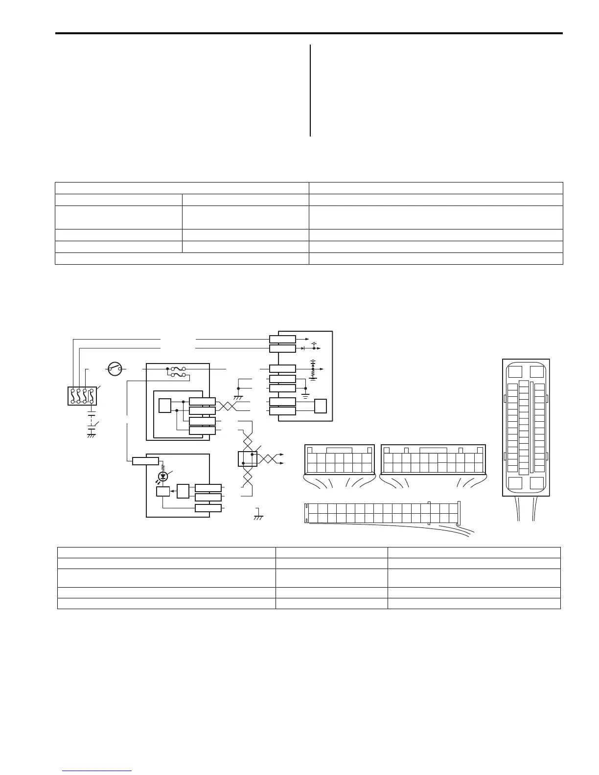
Wiring Diagram
Circuit Description
Operation (ON/OFF) of ESP® warning lamp is controlled by ESP® control module through lamp driver module in
combination meter.
If ESP® system is in good condition, ESP® control module turns ESP® warning lamp ON at the ignition switch ON,
keeps it ON for 2 seconds and then turns it OFF. If an abnormality in the system is detected, ESP® warning lamp is
turned ON continuously by ESP® control module. Also, it is turned ON continuously by lamp driver module when the
connector of ESP® control module is disconnected.
Inspection Item Referring section
Battery Level, leakage “Battery Description in Section 1J”
Connectors of electric wire
harness
Disconnection, friction
“Intermittent and Poor Connection Inspection in Section
00”
Fuses Burning
Brake fluid Level, leakage “Brake Fluid Level Inspection in Section 4A”
Other parts that can be checked visually
[A]
E85
16
1
15
2
3
4
5
6
7
8
9
10
11
12
13
14
17
18
19
20
21
22
23
24
25
26
27
28
29
30
31
32
33
34
35
36
37
38
39
40
41
42
43
44
45
46
47
WHT
GRN
3
E85-13
E85-44
RED
WHT
6
5
E46-1
E46-2
4
10
6
E85-16
E85-47
BLK
BLK
8
9
BLK/ORN
RED
WHT
RED
WHT
G37-4
G37-2
G28-10
G28-8
G28-16
12V
12V
E85-32
E85-1
E85-35
WHT/RED
WHT/BLU
GRN/ORN
6
2
1
7
11
12
[B]
G37E46
1245367
891011121314
1245367
891011
1213141516171819202122
[C]
G28
12345678910111213141516
17181920212223242526272829303132
G28-31
RED/BLK
I6RS0B460010-01
[A]: ESP® control module connector (viewed from terminal side) 3. Ignition switch 8. ESP® warning lamp
[B]: BCM connector (viewed from harness side) 4. Junction block assembly 9. Lamp driver module
[C]: Combination meter connector (viewed from harness side) 5. BCM (included in junction
block assembly)
10. ESP® hydraulic unit / control module assembly
1. Battery 6. CAN driver 11. Junction connector
2. Main fuse box 7. Combination meter 12. To steering angle sensor
 Loading...


