Manual Transmission/Transaxle: 5B-7
3) Apply grease to pin (5) of gear shift control lever, and
then install adjuster (1) into pin of gear shift control
lever securely.
“A”: Grease 99000–25011 (SUZUKI Super
Grease A)
4) Push cable end holder (2) in the direction of A.
NOTE
At this time, do not apply force in the cable
operation direction B to adjuster.
5) Slide lock plate (3) in the direction of C, until it gets
over the claw (4) of cable end holder.
Back Up Light Switch Removal and Installation
S7RS0B5206006
Removal
1) Remove battery and tray with coolant reservoir.
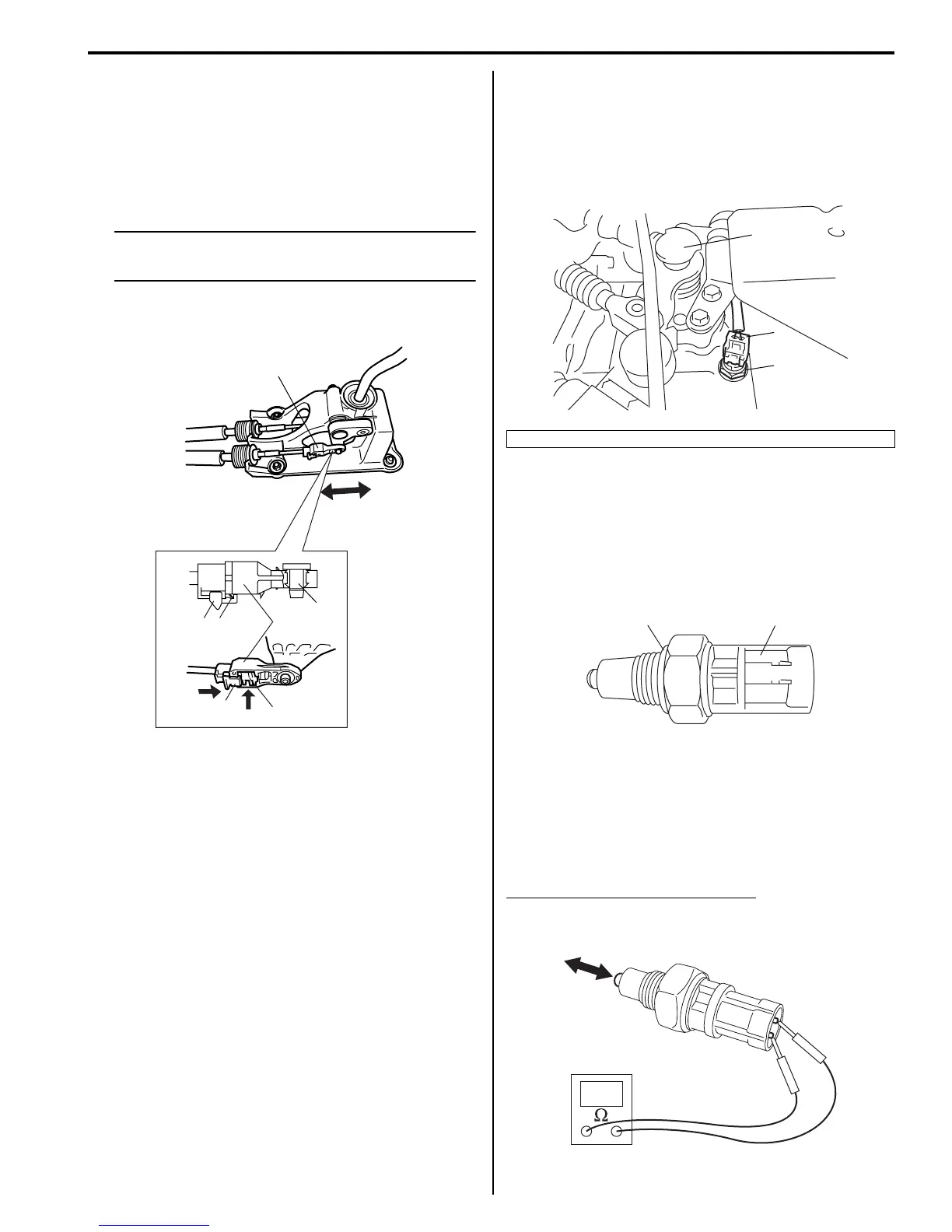
2) Disconnect back up light switch coupler (1).
3) Remove back up light switch (2).
Installation
1) Apply oil to new O-ring (1) and tighten back up light
switch (2) to specified torque.
Tightening torque
Back up light switch (a): 23 N·m (2.3 kgf-m, 17.0
lb-ft)
2) Connect back up light switch coupler.
3) Install battery and tray, and then install coolant
reservoir to battery tray.
Back Up Light Switch Inspection
S7RS0B5206007
Check back up light switch for function using ohmmeter.
Back up light switch specification
Switch ON (Push): Continuity
Switch OFF (Release): No continuity
3
3
4
1
2
A
C
1
B
5, “A”
I4RS0A520005-01
3. Gear shift and select shaft assembly
3
1
2
I4RS0A520010-01
1 2, (a)
I3RH0A520006-01
I4RS0A520011-01
 Loading...


