Power Assisted Steering System: 6C-9
3) Start engine.
4) Read DTC according to the instructions displayed on
SUZUKI scan tool. For further details, refer to
operator’s manual for SUZUKI scan tool.
NOTE
• If communication between SUZUKI scan
tool and the vehicle can not be
established, perform “Serial Data Link
Circuit Check”.
• DTC C1122 (engine speed signal failure) is
indicated when ignition switch is at ON
position and engine is not running, but it
means there is nothing abnormal if
indication changes to a normal one when
engine is started.
5) After completing the check, turn ignition switch to
OFF position and disconnect SUZUKI scan tool from
DLC.
DTC Clearance
S7RS0B6304004
1) Turn ignition switch to OFF position.
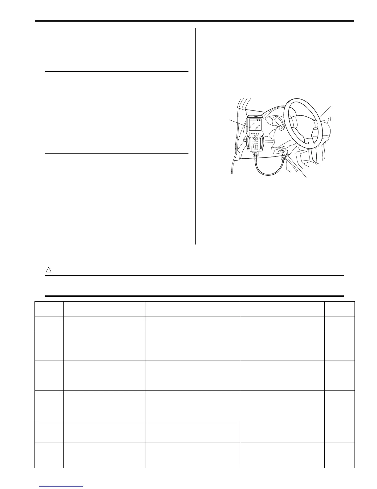
2) Connect SUZUKI scan tool to data link connector
(DLC) (1) located on underside of instrument panel
at driver’s seat side.
Special tool
(A): SUZUKI scan tool
3) Turn ignition switch to ON position.
4) Erase DTC according to the instructions displayed
on SUZUKI scan tool. For further details, refer to
operator’s manual for SUZUKI scan tool.
5) After completing the clearance, turn ignition switch to
OFF position and disconnect SUZUKI scan tool from
DLC.
DTC Table
S7RS0B6304005
CAUTION
!
Be sure to perform the “EPS System Check” before starting troubleshooting corresponding to each
DTC.
(A)
1
I4RS0B450003-01
DTC No. Detecting item
Detecting condition
(DTC will set when detecting)
Trouble area MIL
No
CODES
Normal — — —
) C1113
Steering torque sensor (Main
and Sub) circuit correlation
Voltage difference between torque
sensor main signal and sub signal
is more than 0.6 V for 1 second
continuously.
• Torque sensor signal circuit
• Torque sensor
• P/S control module
1 driving
cycle
) C1114
Steering torque sensor
reference power supply
circuit
Circuit voltage of torque sensor 5
V reference power supply voltage
is more than 5.7 V or less than 4.3
V for 1 second continuously.
• Torque sensor circuit
• Torque sensor
• P/S control module
1 driving
cycle
) C1117
Steering torque sensor
failure signal circuit low
Torque sensor internal failure
signal circuit voltage is less than
1.7 V when ignition switch turned
ON.
• Torque sensor signal circuit
• Torque sensor
• P/S control module
1 driving
cycle
) C1118
Steering torque sensor
failure signal circuit high
Torque sensor internal failure
signal circuit voltage is more than
3.7 V for 1 second continuously.
1 driving
cycle
) C1119
Steering torque sensor
power supply circuit
Circuit voltage of torque sensor
main power supply is less than
7.5 V for 1 second continuously.
• Torque sensor circuit
• Torque sensor
• P/S control module
1 driving
cycle
 Loading...


