1D-17 Engine Mechanical:
Engine Assembly Removal and Installation
S7RS0B1406011
NOTE
After replacing electric throttle body
assembly, perform calibration of throttle
valve referring to “Electric Throttle Body
System Calibration in Section 1C”.
Removal
1) Relieve fuel pressure according to “Fuel Pressure
Relief Procedure in Section 1G”.
2) Disconnect negative and positive cable at battery.
3) Remove battery and tray.
4) Remove engine hood after disconnecting windshield
washer hose.
5) Remove right and left side engine under covers.
6) Remove A/C compressor belt by referring to
“Compressor Drive Belt Removal and Installation in
Section 7B” or “Compressor Drive Belt Removal and
Installation in Section 7B”.
7) Drain engine oil, transaxle oil and coolant.
8) Remove cowl top plate referring to “Cowl Top
Components in Section 9K”.
9) Remove air cleaner assembly referring to “Air
Cleaner Components”.
10) With hose connected, detach A/C compressor from
its bracket (A/C model) referring to “Compressor
Assembly Removal and Installation in Section 7B” or
“Compressor Assembly Removal and Installation in
Section 7B”.
CAUTION
!
Suspend removed A/C compressor at a place
where no damage will be caused during
removal and installation of engine assembly.
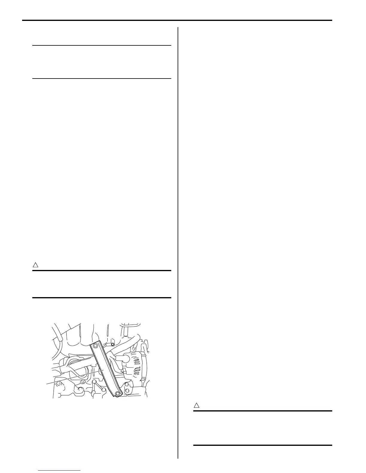
11) Remove intake manifold rear stiffener (1) from intake
manifold and cylinder block.
12) Disconnect the following electric wires:
• MAP sensor (1)
• ECT sensor (2)
•EGR valve (3)
• CMP sensor (4)
• Electric throttle body assembly (5)
• Ignition coil assembly (6)
• Injectors (7)
• Heated oxygen sensor No. 2 (8) and No. 1 (9)
• Oil control valve (10)
• Engine oil pressure switch (11)
• CKP sensor (12)
• Knock sensor (13)
• Back up light switch (14)
• Generator (15)
• Starting motor (16)
• Ground terminal (17) from intake manifold
• Battery ground terminal (18) from exhaust
manifold
• Battery ground cable (19) from transaxle
• Magnet clutch switch of A/C compressor (A/C
model)
• Each wire harness clamps
• Output shaft speed sensor (VSS) (34) (A/T model)
• Solenoid valve (33) (A/T model)
• Transmission range sensor (32) (A/T model)
• Input shaft speed sensor (31) (A/T model)
13) Remove fuse box from its bracket.
14) Disconnect the following cables:
• Gear select control cable (23) (M/T model)
• Gear shift control cable (24) (M/T model)
• A/T select cable (A/T model)
15) Disconnect the following hoses:
• Brake booster hose (26) from intake manifold
• Radiator inlet and outlet hoses (20) from each
pipe
• Heater inlet and outlet hoses (21) from each pipe
• Fuel feed hoses (22) from fuel feed pipe
• EVAP canister purge valve hose (30) from purge
pipe
• A/T fluid cooler hoses (A/T model)
16) With hose connected, detach clutch operating
cylinder (25). (M/T model)
CAUTION
!
Suspend removed clutch operating cylinder
at a place where no damage will be caused
during removal and installation of engine
assembly.
1
I6RS0B141014-01
 Loading...


