Engine General Information and Diagnosis: 1A-81
DTC P0118: Engine Coolant Temperature Circuit High
S7RS0B1104028
Wiring Diagram
Refer to “DTC P0116: Engine Coolant Temperature Circuit Range / Performance”.
DTC Detecting Condition and Trouble Area
NOTE
When DTC P0108 and P0113 are indicated together, it is possible that “ORN” wire circuit open.
DTC Confirmation Procedure
1) With ignition switch turned OFF, connect scan tool.
2) Turn ON ignition switch and clear DTC using scan tool.
3) Start engine and run it for 10 sec. or more.
4) Check DTC and pending DTC.
DTC Troubleshooting
NOTE
• When measuring circuit voltage, resistance and/or pulse signal at ECM connector, connect the
special tool to ECM and/or the ECM connectors referring to “Inspection of ECM and Its Circuits”.
• Upon completion of inspection and repair work, perform “DTC Confirmation Procedure” and
confirm that the trouble has been corrected.
DTC detecting condition Trouble area
ECT sensor output voltage is higher than 4.85 V for 0.5 seconds
continuously.
(Low engine coolant temperature (high voltage/high resistance))
(1 driving cycle detection logic)
• ECT sensor circuit
• ECT sensor
•ECM
Step Action Yes No
1 Was “Engine and Emission Control System Check”
performed?
Go to Step 2. Go to “Engine and
Emission Control
System Check”.
2 ECT sensor and its circuit check
1) Connect scan tool with ignition switch turned OFF.
2) Turn ON ignition switch.
3) Check engine coolant temp. displayed on scan tool.
Is –40
°
C (–40
°
F) indicated?
Go to Step 3. Intermittent trouble.
Check for intermittent
referring to “Intermittent
and Poor Connection
Inspection in Section
00”.
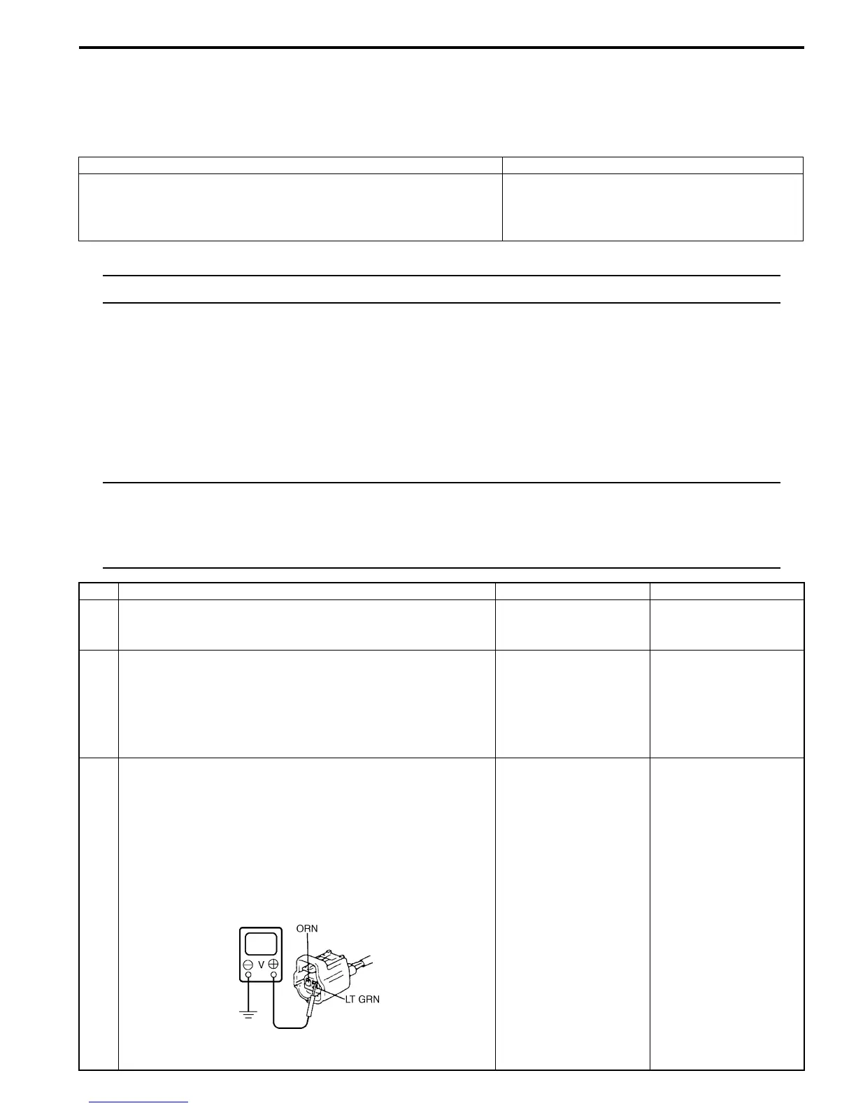
3 ECT voltage check
1) Disconnect connector from ECT sensor with ignition
switch turned OFF.
2) Check for proper connection to ECT sensor at “LT GRN”
and “ORN” wire terminals.
3) If OK, then turn ON ignition switch, measure voltage
between “LT GRN” wire terminal of ECT sensor
connector and vehicle body ground.
Is voltage about 4 – 6 V?
Go to Step 6. Go to Step 4.
I4RS0A110026-01
 Loading...


