Air Conditioning System: Automatic Type 7B-67
Inspection of HVAC Control Module and Its Circuit
S7RS0B7224026
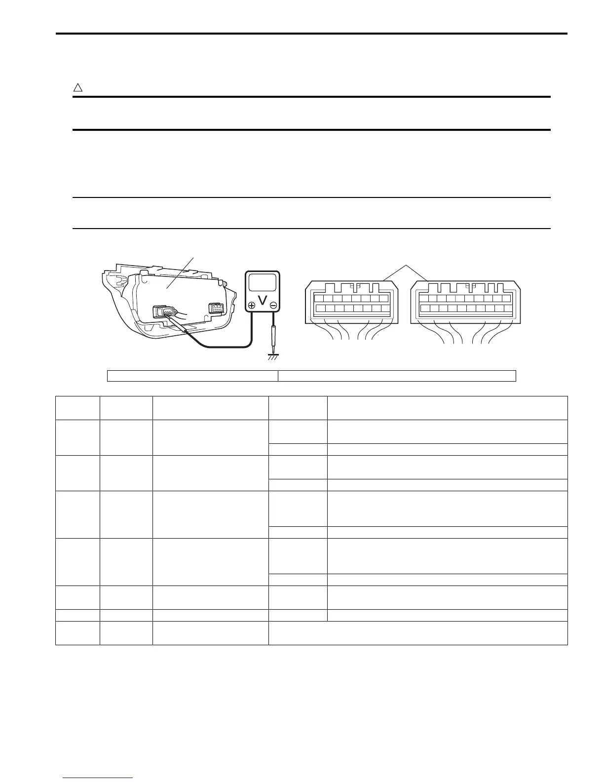
HVAC control module and its circuits can be checked at HVAC control module wiring couplers by measuring voltage.
CAUTION
!
HVAC control module can not be checked by itself. It is strictly prohibited to connect voltmeter to
HVAC control module with couplers disconnected from it.
Voltage Check
1) Remove HVAC control module referring to “HVAC Control Module Removal and Installation”.
2) Check voltage at each terminal.
NOTE
As each terminal voltage is affected by the battery voltage, confirm that it is 11 V or more when ignition
switch is ON.
78
12
910
65 43
1516 14 13 12 11
G52
78
910
1920
12
1112
65 43
1718 16 15 14 13
G51
1
2
I5RS0A722017-02
1. HVAC control module 2. HVAC control module connector (viewed from harness side)
Terminal Wire Color Circuit
Normal
Voltage
Condition
G51-1 BRN/WHT
Air flow control actuator
(DEF)
10 – 14 V
Ignition switch turned ON, air flow control actuator is
working in operation from VENT to DEF position
0 – 1 V Ignition switch turned ON, except the above condition
G51-2 BRN/YEL
Air flow control actuator
(FACE)
10 – 14 V
Ignition switch turned ON, air flow control actuator is
working in operation from DEF to VENT position
0 – 1 V Ignition switch turned ON, except the above condition
G51-3 GRY/BLU
Temperature control
actuator (COOL)
10 – 14 V
Ignition switch turned ON, temperature control
actuator is working in operation from HOT to COOL
position
0 – 1 V Ignition switch turned ON, except the above condition
G51-4 GRY/RED
Temperature control
actuator (HOT)
10 – 14 V
Ignition switch turned ON, temperature control
actuator is working in operation from COOL to HOT
position
0 – 1 V Ignition switch turned ON, except the above condition
G51-5 PPL/WHT
Serial communication line
of data link connector
10 – 14 V Ignition switch turned ON
G51-6 — — — —
G51-7 YEL
Serial communication line
of BCM
Refer to “Inspection of BCM and its Circuits in Section 10B”
 Loading...


