6C-4 Power Assisted Steering System:
Schematic and Routing Diagram
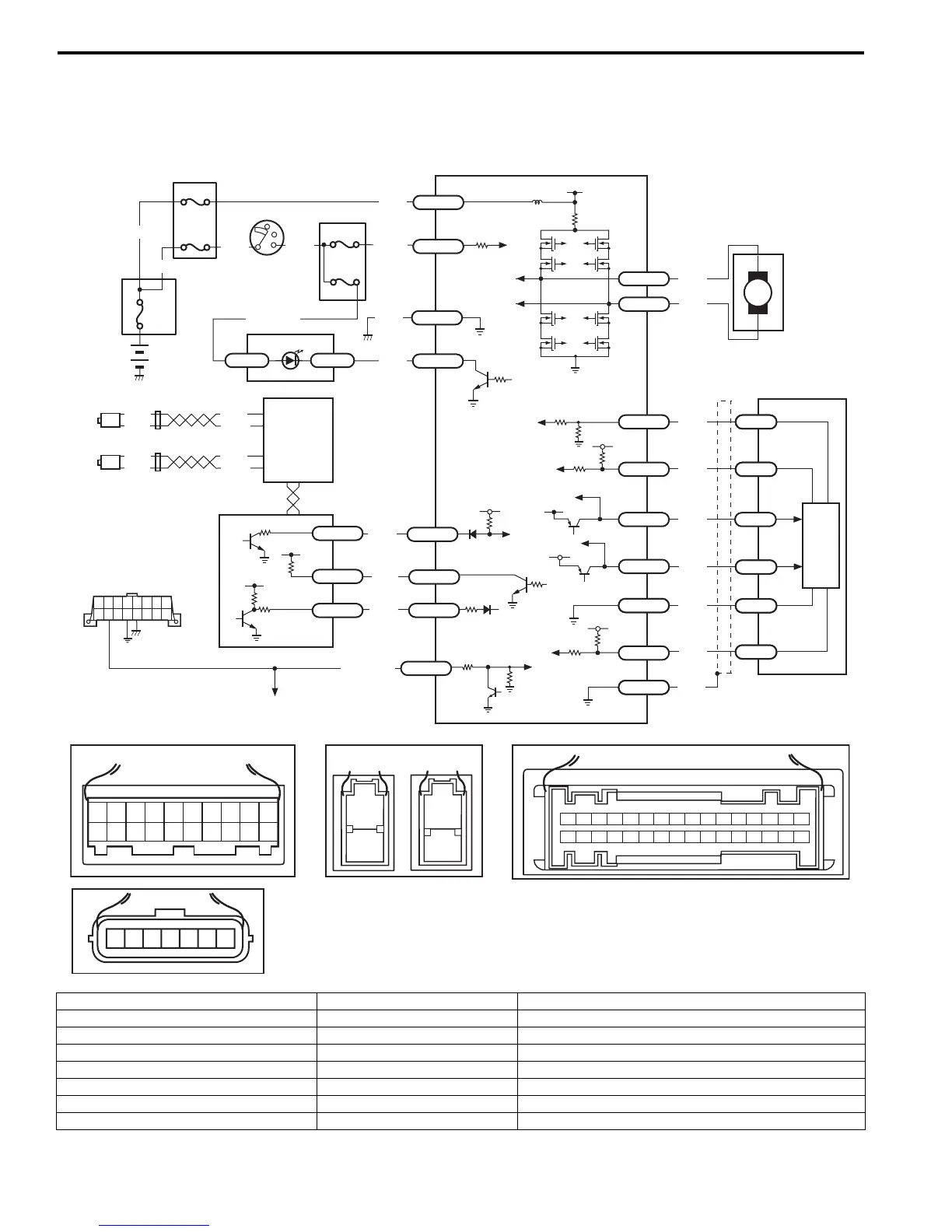
EPS System Wiring Circuit Diagram
S7RS0B6302001
M
5V
BRN
RED/
BLU
BLK
RED
WHT
BLU
GRN
BRN
YEL
E52-11
E52-14
E52-12
E23-4
E23-26
E23-25
E51-1
E51-2
E52-18
E53-5
E53-7
E52-6
E52-8
E53-2
E52-9
E52-16
E52-19
GRY
PPL/WHT
[A]
[E]
12
3
4
5
67
8
9
11
10
12 13
14
15
16
17 18 19
20
1
2
[B]
[C]
1
2
10 9 8 7 654321
16 15 14 13 12 11
26 25 24 23 22 21 20 19 18 17
32 31 30 29 28 27
[D]
5V
PPL
E52-4
11
12
13
14
15
10
9
16
12V
5V
5V
12V
RED
E52-20
E53-6
E53-4
E53-1
7654321
5
RED
RED/
BLK
WHT
6
WHT
WHT/
BLK
WHT
BLK
12V
12V
17
BLK
GRY
LT GRN
/BLK
E52-1
E52-5
E49-1
GRN
GRN
WHT
BLK
WHY
G28-25G28-31
RED/BLK
18
3
4
4
7
8
4
4
1
2
4
E49-2
BLK
I7RS0B630002-01
[A]: Connector “E52” (viewed from harness side) 4. Fuse 12. P/S motor
[B]: Connector “E49” (viewed from harness side) 5. Left-front wheel speed sensor 13. Shield
[C]: Connector “E51” (viewed from harness side) 6. Right-front wheel speed sensor 14. Torque sensor
[D]: Connector “G28” (viewed from harness side) 7. Combination meter 15. Torque sensor amplifier
[E]: Connector “E53” (viewed from harness side) 8. “EPS” warning light 16. To ECM, BCM, Air bag SDM and ABS control module assembly
1. Main fuse box 9. Date link connector (DLC) 17. ABS/ESP® control module
2. Ignition switch 10. ECM 18. Individual circuit fuse box No.1
3. Junction block assembly 11. P/S control module
 Loading...


