9C-15 Instrumentation / Driver Info. / Horn:
Combination Meter Removal and Installation
S7RS0B9306003
Removal
1) Disconnect negative (–) cable at battery.
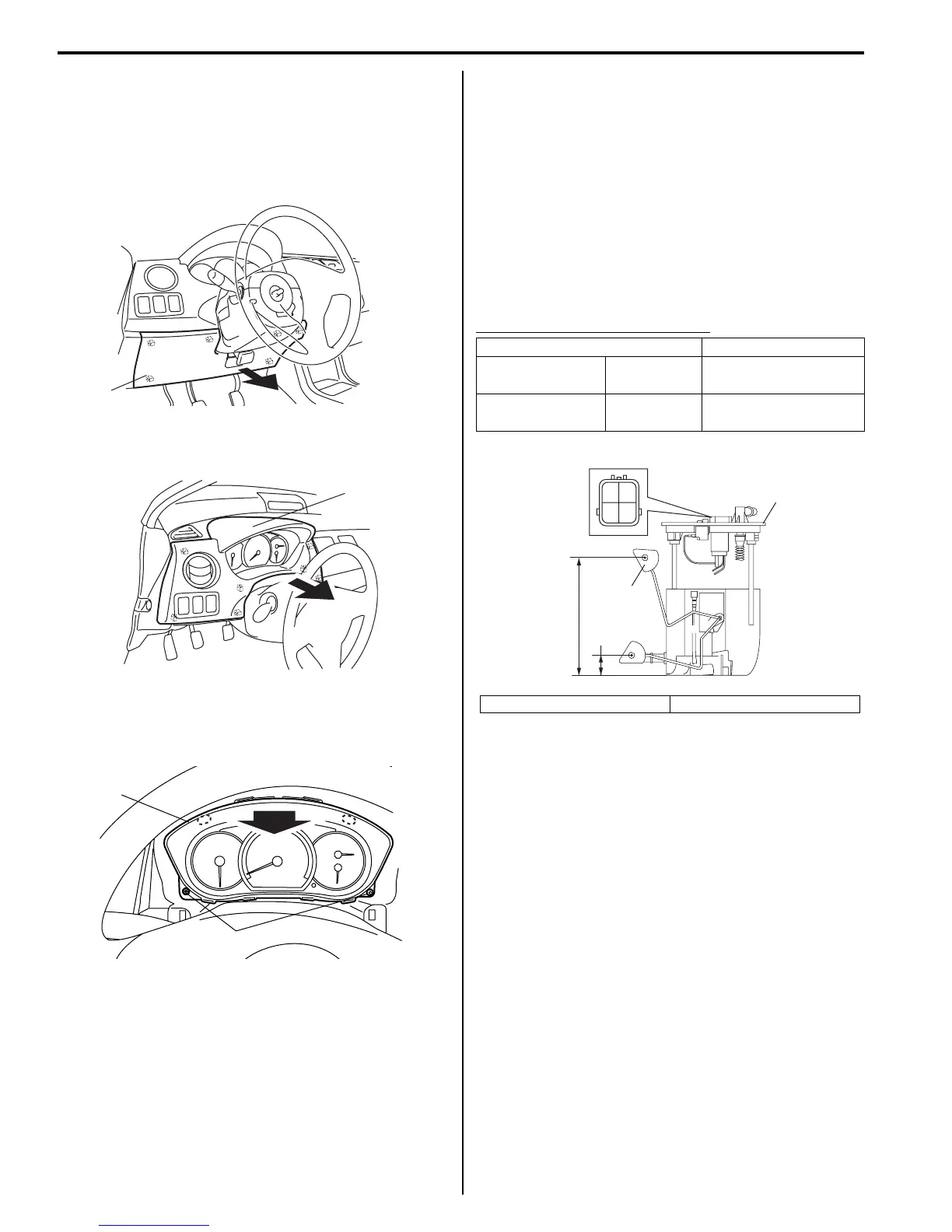
2) Remove steering column hole cover (1) pulling it in
arrow direction shown in figure.
3) Remove combination meter cluster panel (1) pulling
it in arrow direction shown in figure.
4) Remove screws (1) fastening combination meter.
5) Remove combination meter (2) pulling it arrow
direction as shown.
Installation
Reverse removal procedure.
Fuel Level Sensor Removal and Installation
S7RS0B9306004
For removal and installation, refer to “Main Fuel Level
Sensor Removal and Installation in Section 1G”.
Fuel Level Sensor Inspection
S7RS0B9306005
• Check that resistance between terminals “a” and “b”
of fuel level sensor changes with change of float
position.
• Check resistance between terminals “a” and “b” at
each float position in the following.
If the measured value is out of specification, replace.
Fuel level sensor specifications
Oil Pressure Switch Removal and Installation
S7RS0B9306006
For removal and installation, refer to “Oil Pressure
Check in Section 1E”.
1
I4RS0B930005-02
1
I4RS0B930006-02
1
2
I4RS0A930012-02
Float Position Resistance (Ω)
Full Upper “C”
160 mm
(6.30 in.)
40 ± 2
Full Lower “D”
19 mm
(0.75 in.)
280 ± 3.3
1. Fuel pump 2. Float
“b”“a”
2
“C”
“D”
1
I6RS0C930004-01
 Loading...


