EasyManuals Logo

Suzuki SWIFT 2005 User Manual

Suzuki SWIFT 2005
1496 pages
To Next Page IconTo Next Page
To Previous Page IconTo Previous Page
Page #1221 background imageLoading...
Page #1221 background image
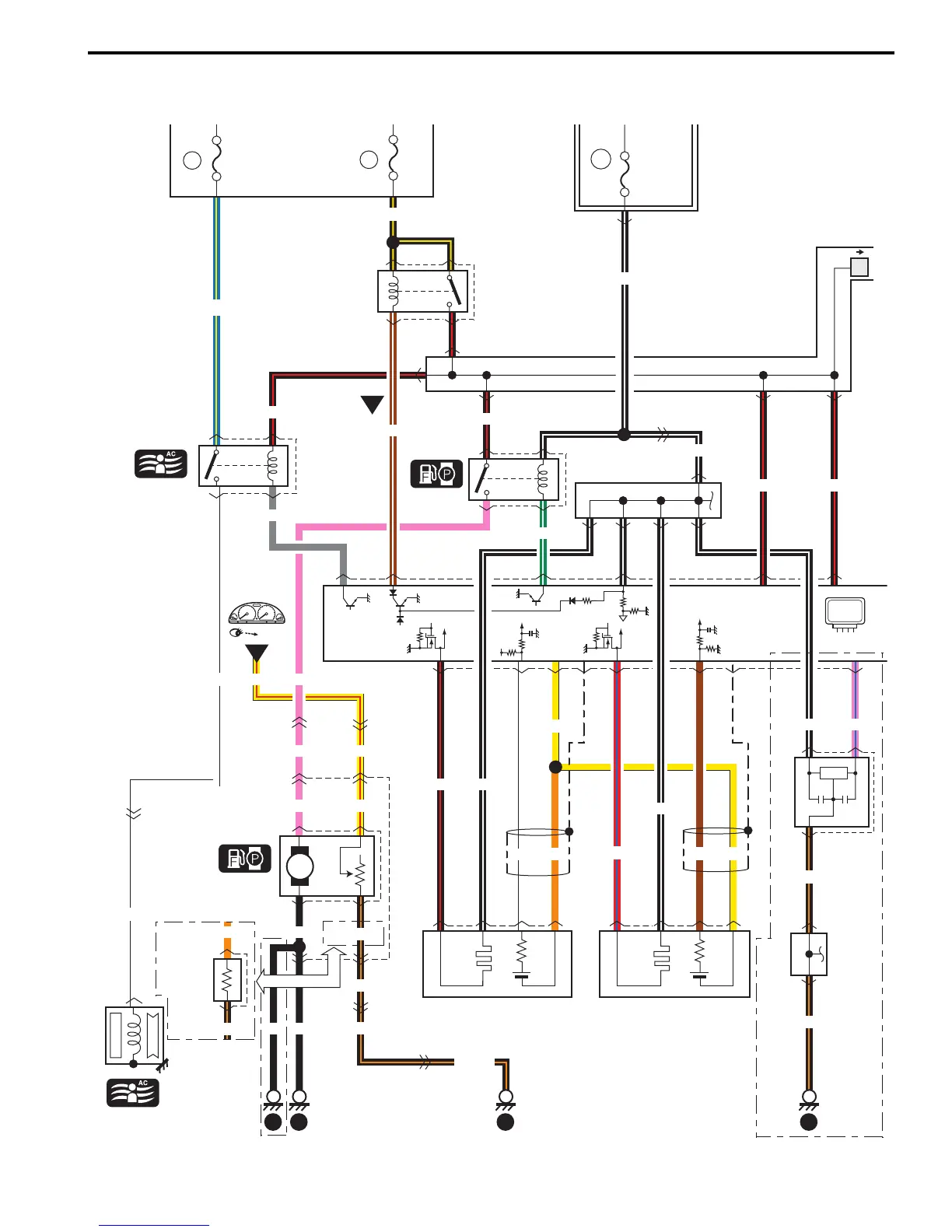
Wiring Systems: 9A-50
A-5 Engine and A/C Control System Circuit Diagram
S7RS0B910E006
YEL/RED
E45
L02
G03
L33
L02
E45
5
8
L15
R01
4
2
PNK
YEL/RED
P
PNK
YEL/RED
31
3
3
1
E24 C36
BLK/ORN
BLK/ORN
BLK/ORN
BLK/ORN
3
15
BLK
42
R02
1
2
R03
And
fuel gauge
Sub fuel
level
sensor
Main
relay
1
BLK/WHT
BLK/WHT
C39
Weld splice
Weld splice
E55
GRN/WHT
IG COIL
J/B
5
15A
FI
BLK/YEL
E32
4
3
2
1
15A
23
BRN/WHT
BW
YR
6
10A
A/C
COMP
Compressor
relay
E36
Relay
BLU/YEL
Compressor
C17
1
E41
5
E24 C36
3
E24
C36
11
BLK/WHT
C15
C16
Heated oxygen
sensor #1
BLK/RED
WHT
Heated oxygen
sensor #2
BRN
BLK/WHT
RED/BLU
C37
3421
3421
46
10
57
47
11
YEL
51
23
PNK
ECM
4
1
3
2
WHT
WHT
BLK/RED
BLK/RED
BLK/RED
E23
47
60
15
29
1
GRY
E35
2
3
1
4
ORN
BLKBLK
BLK/ORN
ORN
YEL
50
BLK/RED
16
1721 3
Individual circuit
fuse box (No.1)
BLK/ORN
BLK/ORN
BLK/WHT PNK/BLU
IF EQPD
IF EQPD
IF EQPD
Weld
splice
C40
C32
Current
sensor
3
2
1
"C-3"
I7RS0B910912-01

Table of Contents

Questions and Answers:

Question and Answer IconNeed help?

Do you have a question about the Suzuki SWIFT 2005 and is the answer not in the manual?

Suzuki SWIFT 2005 Specifications

General IconGeneral
BrandSuzuki
ModelSWIFT 2005
CategoryAutomobile
LanguageEnglish

Related product manuals