Engine General Information and Diagnosis: 1A-11
Generator Control System Description
S7RS0B1101010
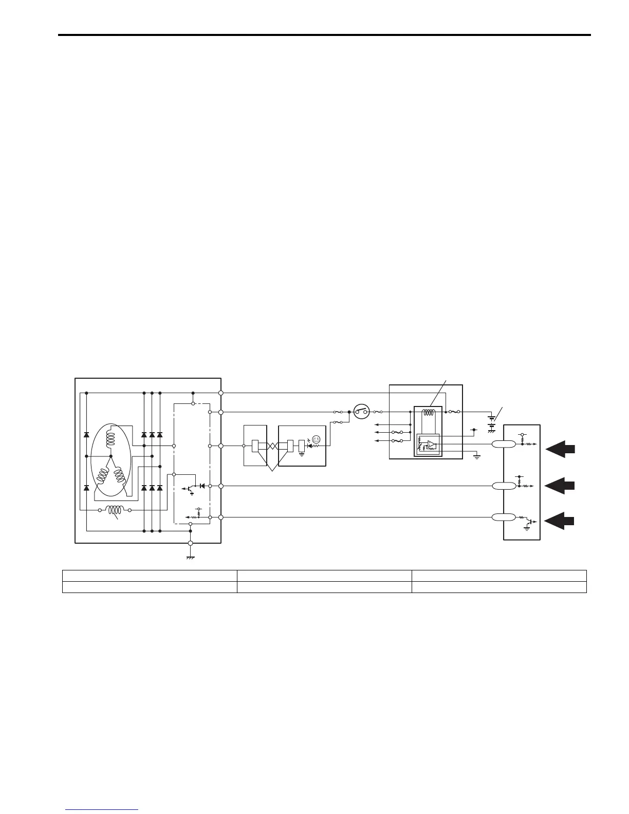
Generator Control System consists of a generator (1), electric load current sensor (7) located in the main fuse box (4)
and ECM (5).
ECM controls generated electricity (adjusting voltage of IC regulator (2)) so that it is suitable for the engine and electric
load conditions. When the electric load increases quickly, generation load of the generator increases quickly and
causes idling to change. To prevent this, ECM makes generated electricity volume vary gradually to stabilize idling.
Also, it reduces the engine load caused by temporary increase in electricity generation to cope with the engine
condition (such as when accelerating).
Operation
ECM controls the generated voltage of the generator using “C” terminal (generator control terminal) duty, based on
following information.
• Engine condition (ECT, vehicle speed, engine speed, TP, etc.) (9)
• Battery voltage (ECM backup power voltage) (10)
• Electric load condition (blower motor, rear defogger, head lights, radiator fan, A/C, etc.) (11)
• “FR” terminal output (field coil (3) control duty) which indicates the operation rate (electricity generation condition) of
the generator.
Then the generator uses “C” terminal duty to regulate the adjusting voltage of the IC regulator with the field coil control
duty so as to control its generated voltage (“B” terminal output voltage).
(For more information of the generated voltage, refer to “Charging System Specifications in Section 1J”.)
Furthermore, the generation condition of the generator is controlled to the optimum level by the electric load current
sensor (7) which detects the electrical load condition (current consumption) linearly even when a sudden electrical
load variation occurs and thus the engine load is reduced.
B
IG
L
C
E
6
2
3
FR
5
12
13
14
1
IG1
7
4
8
11
10
9
CMO
FCD
GCD
I6RW0H110005-01
6. Ignition switch 12. BCM 14. CAN driver
8. Battery 13. Combination meter
 Loading...


