1D-25 Engine Mechanical:
Timing Chain and Chain Tensioner Removal
and Installation
S7RS0B1406018
Removal
CAUTION
!
After timing chain is removed, never turn
crankshaft and camshafts independently
more than its allowable turning range
described in “Installation”.
If turned, interference may occur between
piston and valves and valves themselves,
and parts related to piston and valves may be
damaged.
1) Remove timing chain cover referring to “Timing
Chain Cover Removal and Installation”.
2) By turning crankshaft, align camshafts and
crankshaft at specific position as follows.
a) Align both intake and exhaust camshaft timing
sprocket marks (1) with notches (2) of cylinder
head respectively.
b) Align crankshaft sprocket key (3) with notch of
cylinder block (4).
Position crankshaft sprocket key (3) at upside of
crankshaft as shown in figure.
3) Remove timing chain tensioner adjuster assembly
(5).
4) Remove timing chain tensioner (6).
5) Remove timing chain No.1 guide (7).
6) Remove timing chain (8) with crankshaft timing
sprocket (9).
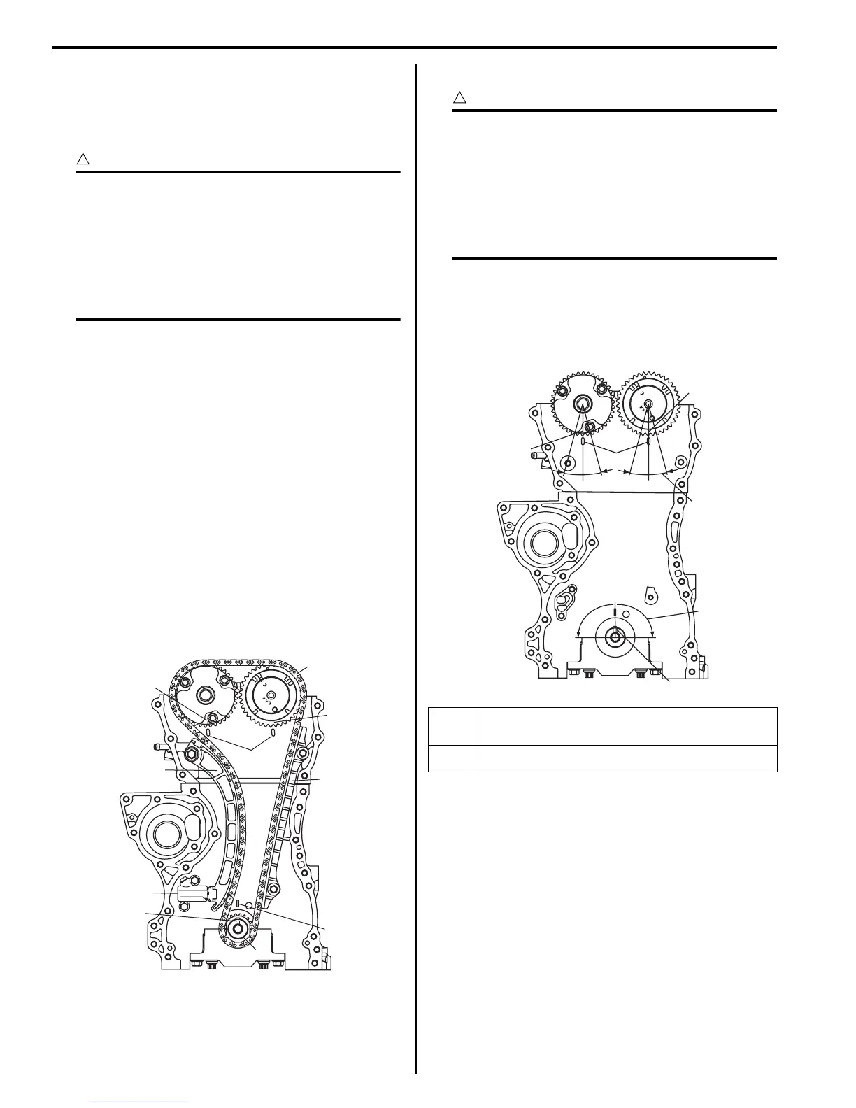
Installation
CAUTION
!
After timing chain is removed, never turn
crankshaft and camshafts independently
more than such an extent (“a”, “b”) as shown
in figure.
If turned, interference may occur between
piston and valves and valves themselves,
and parts related to piston and valves may be
damaged.
1) Check that match marks (1) on intake and exhaust
camshaft timing sprockets are in match with notches
(2) on cylinder head as shown in figure.
2) Set key (3) and turn crankshaft to position key on
upside of crankshaft.
3
4
1
1
2
5
6
7
8
9
I3RH0B140032-01
“a”: 90° 4. Camshaft (IN and EX) allowable turning range.
By marks on camshaft timing sprocket within 15° from notches
on cylinder head on both right and left.
“b”: 15° 5. Crankshaft allowable turning range.
By key on crankshaft, within 90° from top on both right and left.
“a”
“b”
“b”
“b”
“b”
“a”
1
1
2
4
3
5
I4RS0A140021-01
 Loading...


