1A-168 Engine General Information and Diagnosis:
DTC P2135: Throttle / Pedal Position Sensor / Switch “A”/“B” (Main / Sub) Voltage Correlation
S7RS0B1104076
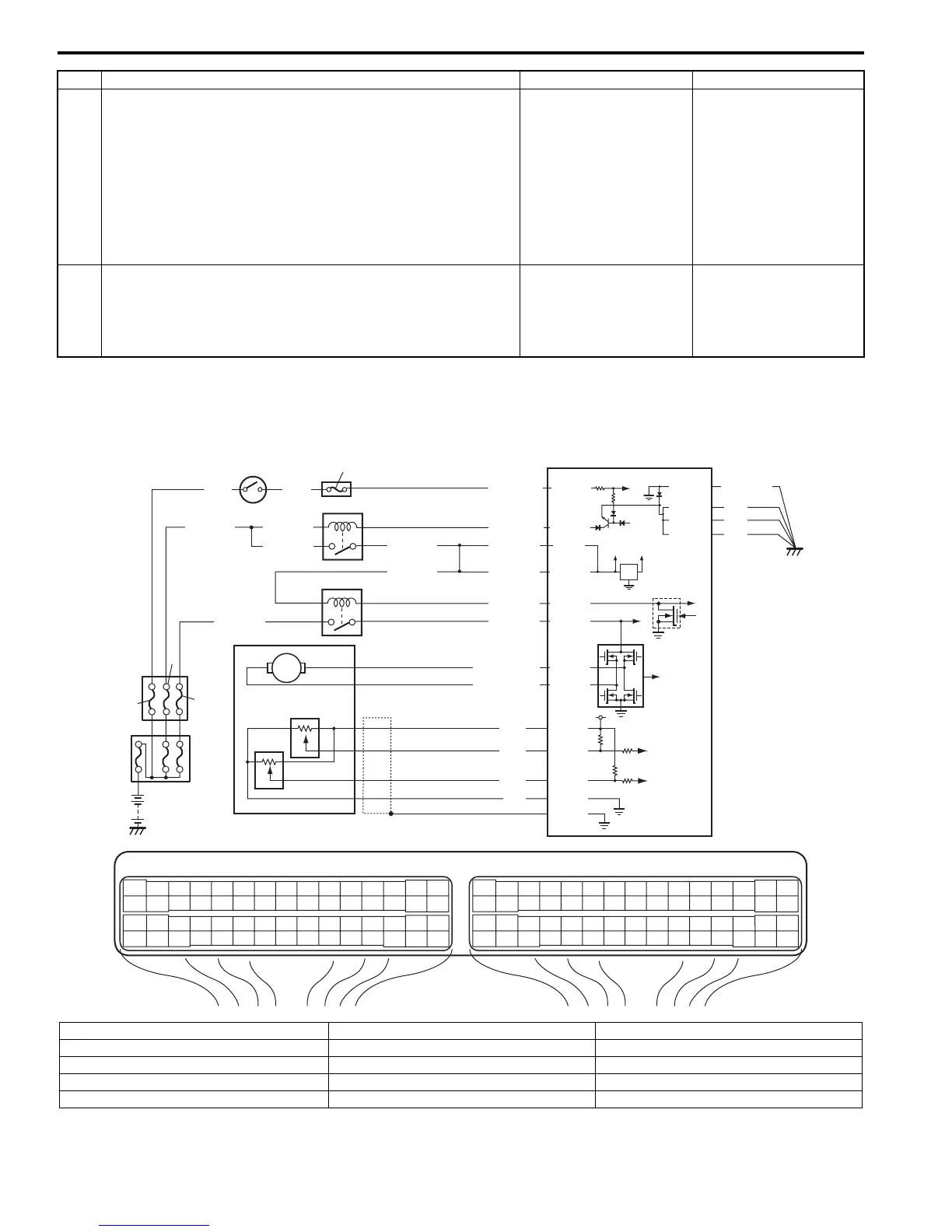
Wiring Diagram
9 Ground circuit check
1) Remove ECM from its bracket with ECM connectors
connected.
2) Check for proper connection of ECM connector at “E23-
51” terminal.
3) If OK, measure resistance between “E23-51” terminal of
ECM connector and engine ground.
Is resistance below 5
Ω
?
“WHT” wire is open or
high resistance circuit.
Faulty ECM ground
circuit. If circuit is OK,
substitute a known-
good ECM and recheck.
10 APP sensor check
1) Check APP sensor (sub) referring to “APP Sensor
Assembly Inspection in Section 1C”.
Is output voltage within specified value?
Substitute a known-
good ECM and recheck.
Replace APP sensor.
Step Action Yes No
E23 C37
34
1819
5671011
1720
47 46495051
2122
52
1625
9
24
14
29
5557 54 53
59
60 58
2
262728
15
30
56 48
32 31343536374042 39 38
44
45 43 41 33
11213
23
834
1819
5671011
1720
47 46495051
2122
52
1625
9
24
14
29
5557 54 53
59
60 58
2
262728
15
30
56 48
32 31343536374042 39 38
44
45 43 41 33
11213
23
8
12V
5V
BLK/REDBLK/RED
BLK/YEL
1
2
BLK/YEL
BLK/YEL
BRN/WHT
E23-1
E23-60
C37-58
C37-15
C37-30
BLK/ORN
BLK
BLK
E23-31
BLK
BLK/RED
BLU/ORN
RED/YEL
YEL/BLU
LT GRN/RED
LT GRN/BLK
RED
GRN
WHT
BLK
E23-16
E23-45
E23-32
C37-45
C37-44
C37-41
C37-42
C37-40
C37-54
C37-43
1-1
1-2
1-3
3
4
5
8
6
7
10
9
E23-29
GRN
BLK/WHT
WHT
BLK/RED
I6RS0C110045-01
1. Electric throttle body assembly 3. ECM 8. “IG ACC” fuse
1-1. Throttle actuator 4. Main relay 9. “IG COIL” fuse
1-2. TP sensor (main) 5. Individual circuit fuse box No.1 10. Ignition switch
1-3. TP sensor (sub) 6. “TH MOT” fuse
2. Throttle actuator control relay 7. “FI” fuse
 Loading...


