4F-8 Electronic Stability Program:
Schematic and Routing Diagram
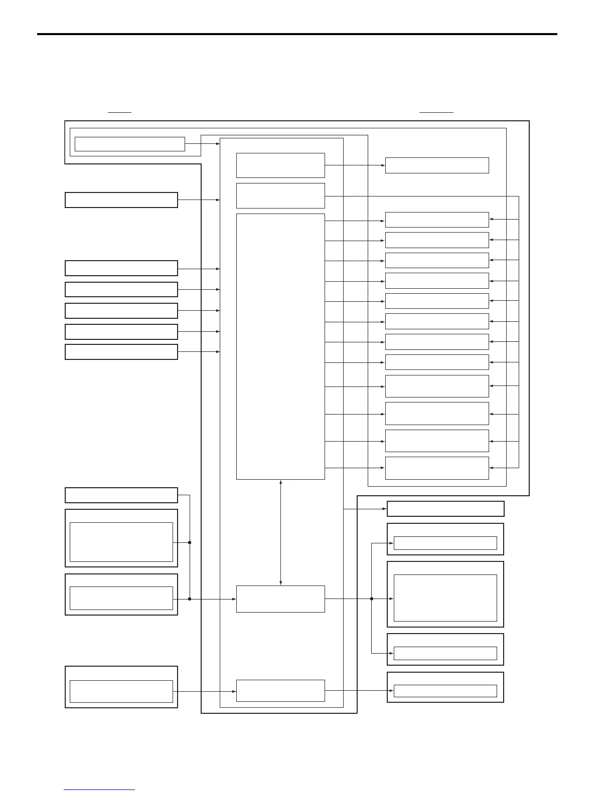
Electronic Stability Program Schematic
S7RS0B4602001
INPUT OUTPUT
ESP® control module
Wheel speed sensor (LF)
Wheel speed sensor (LR)
Wheel speed sensor (RF)
Battery Voltage
Master cylinder pressure sensor
Pump motor driver
(transistor)
Solenoid valve power
supply driver (transistor)
Solenoid valve driver
(transistor)
CAN driver
CAN driver (for yaw rate /
G sensor assembly)
Hydraulic unit
Pump motor
LF inlet solenoid valve
LF outlet solenoid valve
LR inlet solenoid valve
LR outlet solenoid valve
RF inlet solenoid valve
RF outlet solenoid valve
RR inlet solenoid valve
RR outlet solenoid valve
Data link connector
Data link connector
ESP® hydraulic unit/control module assembly
Wheel speed sensor (RR)
Master cylinder cut solenoid
valve No. 1
Master cylinder cut solenoid
valve No. 2
Low pressure solenoid valve
No. 1
Low pressure solenoid valve
No. 2
Stop lamp switch
Engine torque
Accelerator pedal position
Engine speed
ECM
Brake fluid level switch
Parking brake switch
BCM
Steering angle sensor
ESP® OFF switch
Yaw rate
Lateral G
Yaw rate / G sensor assembly
ABS warning lamp
EBD warning lamp
ESP® warning lamp
SLIP indicator lamp
ESP® OFF lamp
Combination meter
Torque request
ECM
Steering angle neutral position
Steering angle sensor
Yaw rate / G sensor assembly
Lateral G neutral position
I7RS0B460006-01
 Loading...


