Engine General Information and Diagnosis: 1A-145
DTC Troubleshooting
NOTE
• When measuring circuit voltage, resistance and/or pulse signal at ECM connector, connect the
special tool to ECM and/or the ECM connectors referring to “Inspection of ECM and Its Circuits”.
• Upon completion of inspection and repair work, perform “DTC Confirmation Procedure” and
confirm that the trouble has been corrected.
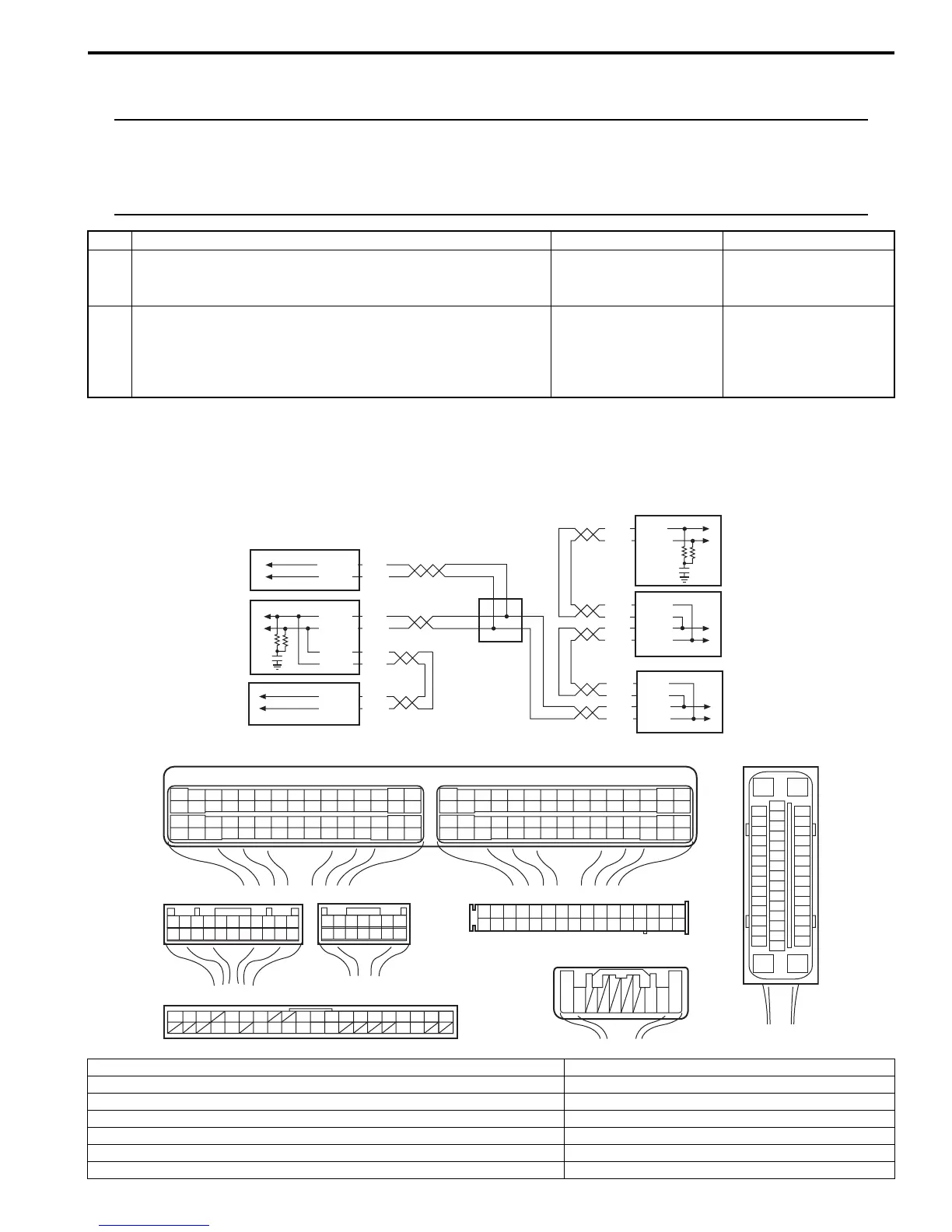
DTC P1674: CAN Communication (Bus Off Error)
S7RS0B1104062
Wiring Diagram
ESP® model
Step Action Yes No
1 Was “Engine and Emission Control System Check”
performed?
Go to Step 2. Go to “Engine and
Emission Control
System Check”.
2 DTC check
1) Check DTC of TCM referring to “DTC Check in Section
5A”.
Is there any DTC(s)?
Go to applicable DTC
diag. flow.
Substitute a known-
good ECM and recheck.
[F]
E85
16
1
15
2
3
4
5
6
7
8
9
10
11
12
13
14
17
18
19
20
21
22
23
24
25
26
27
28
29
30
31
32
33
34
35
36
37
38
39
40
41
42
43
44
45
46
47
[D]
1234567891011141516
36 34 33 32 31 30 29 24 2337
181920
G49
[A]
E23 C37
34
1819
5671011
17
20
47 46
495051
2122
52
16
25
9
24
14
29
5557 54 53
59
60
58
2
262728
15
30
56
48
32 31
343536374042 39 38
44
45
43 41 33
1
1213
23
8
34
1819
5671011
17
20
47 46
495051
2122
52
16
25
9
24
14
29
5557 54 53
59
60 58
2
262728
15
30
56
48
32 31
343536374042 39 38
44
45
43 41 33
1
1213
23
8
[C]
G28
1234567
8
910111213141516
1718
19
20
212223242526272829303132
[E]
G54
109 321
[B]
G37
E46
1234567
1234567
891011
891011121314 1213141516171819202122
4
6
1
2
3
RED
WHT
RED
WHT
RED
WHT
RED
WHT
RED
WHT
E23-3
E23-18
E85-42
E85-46
E85-13
E85-44
E46-1
E46-2
G37-4
G37-2
RED
WHT
RED
WHT
G49-19
G49-18
5
7
WHTG54-9
REDG54-10
G28-8
G28-10
G28-7 RED
G28-9 WHT
I7RS0B110014-02
[A]: ECM connector (viewed from harness side) 1. ECM
[B]: BCM connector (viewed from harness side) 2. ESP® control module
[C]: Combination meter connector (viewed from harness side) 3. BCM
[D]: Keyless start control module connector (viewed from harness side) 4. Steering angle sensor
[E]: Steering angle sensor connector (viewed from harness side) 5. Combination meter
[F]: ESP® control module connector (viewed from terminal side) 6. Keyless start control module
7. CAN junction connector
 Loading...


