5A-48 Automatic Transmission/Transaxle:
Table for Step 4
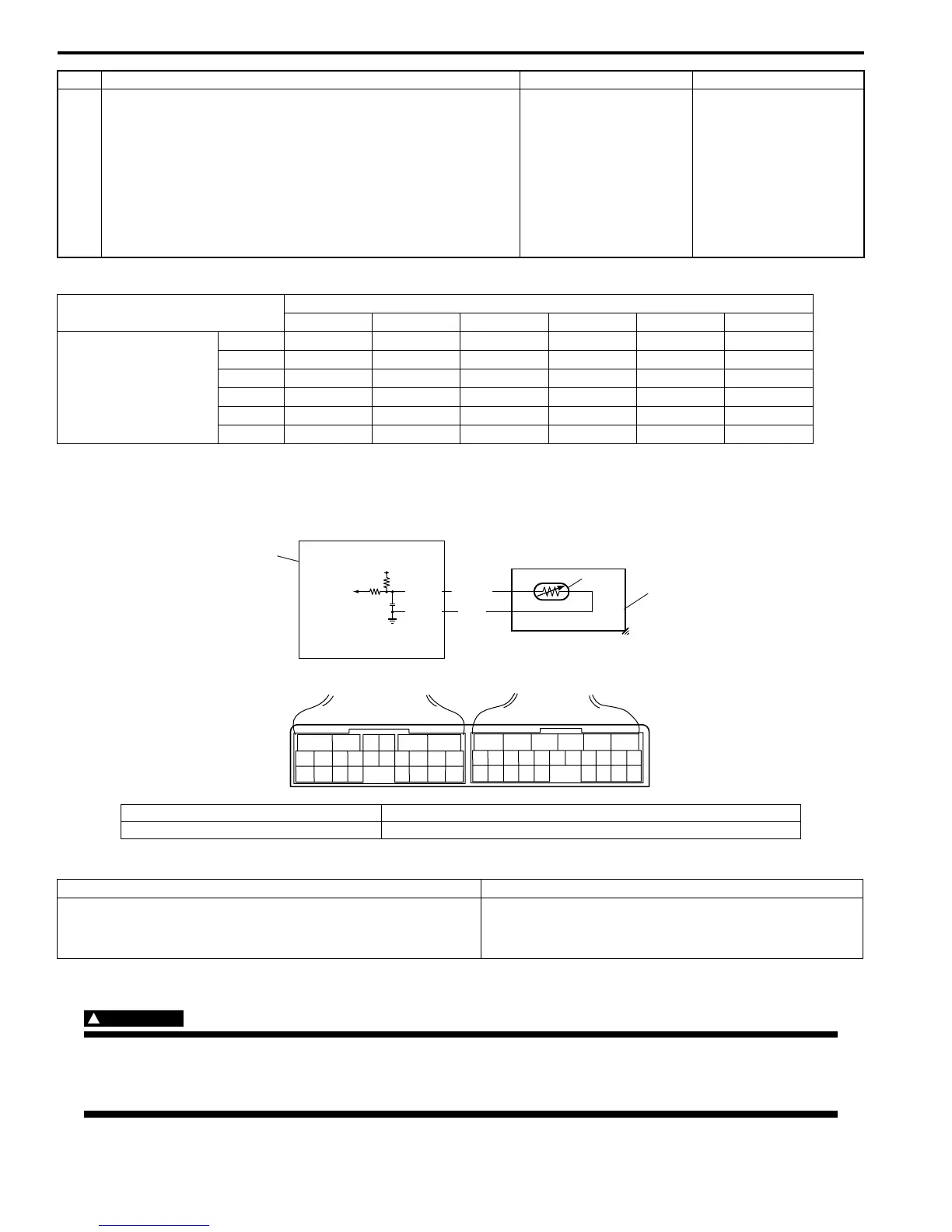
DTC P0712: Transmission Fluid Temperature Sensor “A” Circuit Low
S7RS0B5104025
Wiring Diagram
DTC Detecting Condition and Trouble Area
DTC Confirmation Procedure
WARNING
!
• When performing a road test, select a place where there is no traffic or possibility of a traffic
accident and be very careful during testing to avoid occurrence of an accident.
• Road test should be carried out with 2 persons, a driver and a tester, on a level road.
7 1) Check transmission range sensor (switch) referring to
“Transmission Range Sensor (Shift Switch) Inspection
and Adjustment”.
Are check results satisfactory?
“RED/BLK”, “PNK/BLK”,
“RED”, “GRN/ORN”,
“GRN”, “GRN/YEL” or
“LT GRN/BLK” circuit
open or short to ground.
If wires and connections
are OK, substitute a
know-good TCM and
recheck.
Replace transmission
range sensor.
Step Action Yes No
Terminal
C35-20 C35-1 C35-8 C35-7 C35-19 C35-18
Select lever position
P8 – 14 V0 V0 V0 V0 V0 V
R 0 V 8 – 14 V 0 V 0 V 0 V 0 V
N 0 V 0 V 8 – 14 V 0 V 0 V 0 V
D or 3 0 V 0 V 0 V 8 – 14 V 0 V 0 V
20 V0 V0 V0 V8 – 14 V0 V
L0 V0 V0 V0 V0 V8 – 14 V
5V
C34-11
C34-12
LT GRN
ORN
2
3
12 11
C34
C35
[A]
1
I4RS0A510011-01
1. TCM 3. A/T
2. Transmission fluid temperature sensor 4. Terminal arrangement of TCM connector (viewed from harness side)
DTC detecting condition Trouble area
Transmission temperature sensor terminal voltage is less
than specified value for 5 minutes or more after turning
ignition switch ON.
• Transmission fluid temperature sensor or its circuit
malfunction
•TCM
 Loading...


