ABS: 4E-16
Serial Data Link Circuit Check
S7RS0B4504011
Inspection
WHT/BLU
BLK
12V
12
BLK
E03-14
E03-13
E03-26
WHT/RED
GRN/ORN
E03-7
WHT/BLU
GRN
1
2
3
4
7
RED/BLK
6
5
11
E03-1
12V
[A]
E03
15
16
17
18
19
20
21
22
23
24
25
2
3
4
5
6
7
8
9
10
11
12
1
13
14
26
BLK/ORN
PPL/WHT
8
E03-5
9
12V
+BB
G
B
G1
E03-12
E03-6
RED
WHT
11
G28-8
G28-10
RED
WHT
E46-1
E46-2
RED
RED
WHT
WHT
10
11
G37-2
G37-4
I6RS0C450008-01
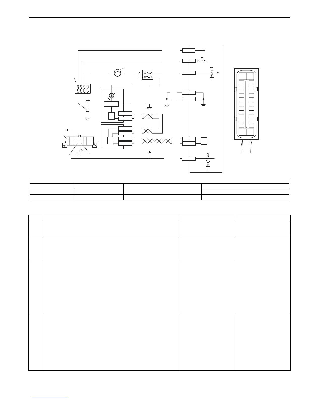
[A]: ABS hydraulic unit / control module connector (viewed from terminal side)
1. Battery 4. Circuit fuse box 7. Lamp driver module 10. BCM
2. Main fuse box 5. Combination meter 8. Data link connector (DLC) 11. CAN driver
3. Ignition switch 6. ABS warning light 9. To ECM, BCM and SDM 12. ABS hydraulic unit / control module assembly
Step Action Yes No
1 1) Turn ignition switch to ON position.
Does ABS warning light come ON?
Go to Step 2. Go to Step 6.
2 1) Turn ignition switch to OFF position.
Are main fuses for ABS pump motor and ABS solenoid in
good condition?
Go to Step 3. Replace fuse and check
for short.
3 1) Disconnect ABS hydraulic unit / control module
connector.
2) Check for proper connection to ABS hydraulic unit /
control module connector at terminal “E03-7”.
3) If OK then turn ignition switch to ON position and
measure voltage between terminal “E03-7” and vehicle
body ground.
Is it 10 – 14 V?
Go to Step 4. “GRN/ORN” wire circuit
open.
4 1) Turn ignition switch to OFF position.
2) Check for proper connection to ABS hydraulic unit /
control module connector at terminals “E03-1” and “E03-
14”.
3) If OK then turn ignition switch to ON position and
measure voltage between each terminal of “E03-1”,
“E03-14” and vehicle body ground.
Are they 10 – 14 V?
Go to Step 5. “WHT/RED” and / or
“WHT/BLU” wire circuit
open.
 Loading...


