10E-28 Keyless Start System:
DTC No. 51 / No. 52 / No. 53: Driver Side / Passenger Side / Rear End Door Request Switch Failure
S7RS0BA504022
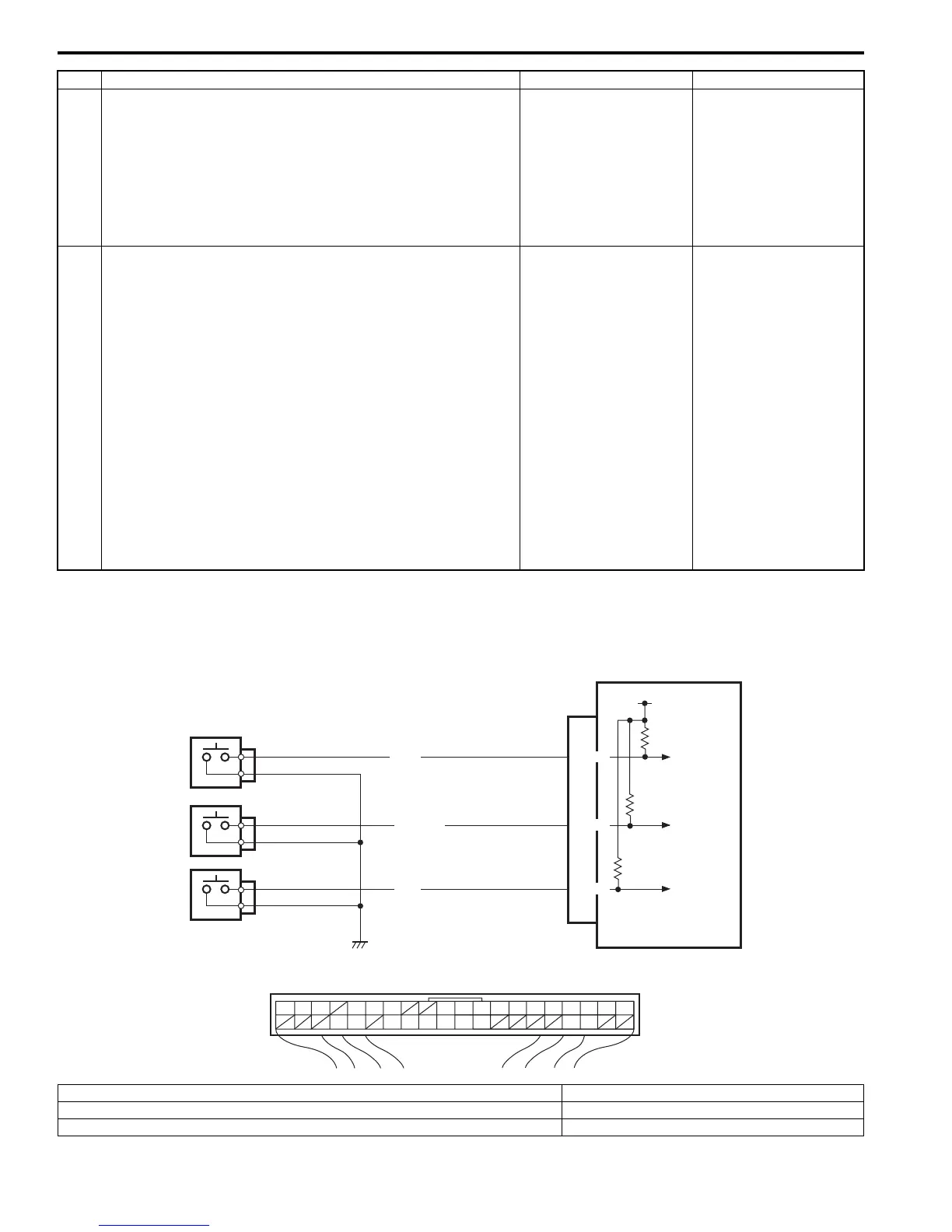
Wiring Diagram
3 CAN communication circuit check
1) Turn ignition switch to OFF position.
2) Disconnect connectors of all control modules
communicating by means of CAN.
3) Check CAN communication circuit between control
modules for open, short and high resistance.
Is each CAN communication circuit in good condition?
Go to Step 4. Repair circuit.
4 DTC check of keyless start control module
1) Turn ignition switch to OFF position.
2) Connect connectors of disconnected control modules
communicating by means of CAN.
3) Disconnect connector of any one control module other
than keyless start control module.
4) Recheck keyless start control module for DTC.
Is DTC No.33 detected?
Using same method,
disconnect connectors
of control module other
than keyless start
control module one by
one to check if DTC
No.33 is detected.
If DTC No.33 is
detected even through
connector of control
module other than
keyless start control
module is disconnected,
substitute a known-
good keyless start
control module and
recheck.
Check power and
ground circuit of
disconnect control
module. If circuit is OK,
substitute a known-
good disconnected
control module and
recheck.
Step Action Yes No
PPL
BLU/RED
YEL
G42-16
G42-36
G42-32
12V
1234567891011141516
36 34 33 32 31 30 29 24 2337
181920
1
2
3
4
[A]
I4RS0BA50026-01
[A]: Keyless start control module connector (viewed from harness side) 3. Passenger side door request switch
1. Keyless start control module 4. Rear end door request switch
2. Driver side door request switch
 Loading...


