Engine General Information and Diagnosis: 1A-47
MIL Does Not Come ON with Ignition Switch ON and Engine Stop (but Engine Can Be Started)
S7RS0B1104011
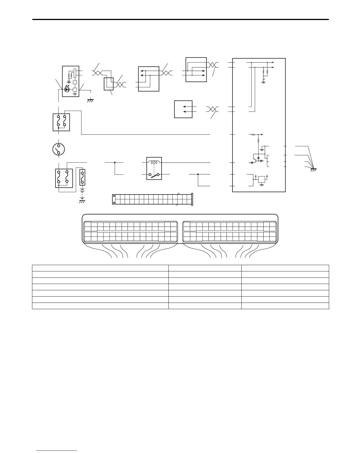
Wiring Diagram
Circuit Description
When the ignition switch is turned ON, ECM causes the main relay to turn ON (close the contact point). Then, ECM
being supplied with the main power, transmits indication ON signal of MIL to combination meter in order to turn MIL
ON. And then, combination meter turns MIL ON. When the engine starts to run and no malfunction is detected in the
system, ECM transmits MIL indication OFF signal to combination meter in order to turn MIL OFF. And then,
combination meter turns MIL OFF, but if a malfunction was or is detected, MIL remains ON even when the engine is
running.
G28
1234567
8
910111213141516
1718
19
20
212223242526272829303132
[B]
[A]
E23 C37
34
1819
5671011
17
20
47 46
495051
2122
52
16
25
9
24
14
29
5557 54 53
59
60
58
2
262728
15
30
56
48
32 31
343536374042 39 38
44
45
43 41 33
1
1213
23
8
34
1819
5671011
17
20
47 46
495051
2122
52
16
25
9
24
14
29
5557 54 53
59
60 58
2
262728
15
30
56
48
32 31
343536374042 39 38
44
45
43 41 33
1
1213
23
8
BLK/WHT
BLK/RED BLK/RED
BRN/WHT
BLK/RED
WHT
BLK/YEL
GRN
12V
5V
2
3
8
6
7
E23-29
E23-3
E23-1
E23-60
E23-18
E23-16
10
14
14
12
11
RED/BLK
C37-58
C37-15
C37-30
BLK
E23-31
BLK
BLK/ORN
BLK/ORN
4
WHT
RED
WHT
RED
BLK/ORN
G28-16
15
13
14
14 14
G28-31
BLK/YEL
BLK/YEL
WHT
RED
WHT
RED
WHT
RED
C37-13
C37-12
WHT
RED
9
17
5
1
16
I7RS0B110012-02
[A]: ECM connector (viewed from harness side) 6. “METER” fuse 13. TCM (A/T model)
[B]: Combination meter connector (viewed from harness side) 7. ECM 14. CAN communication line
1. Main fuse box 8. Junction block assembly 15. ABS/ESP® control module
2. Ignition switch 9. BCM 16. CAN junction connector (ESP® model)
3. Main relay 10. “FI” fuse 17. Combination meter
4. Malfunction indicator lamp in combination meter 11. Individual circuit fuse box No.1
5. “IG COIL” fuse 12. “IG ACC” fuse
 Loading...


