1H-2 Ignition System:
Schematic and Routing Diagram
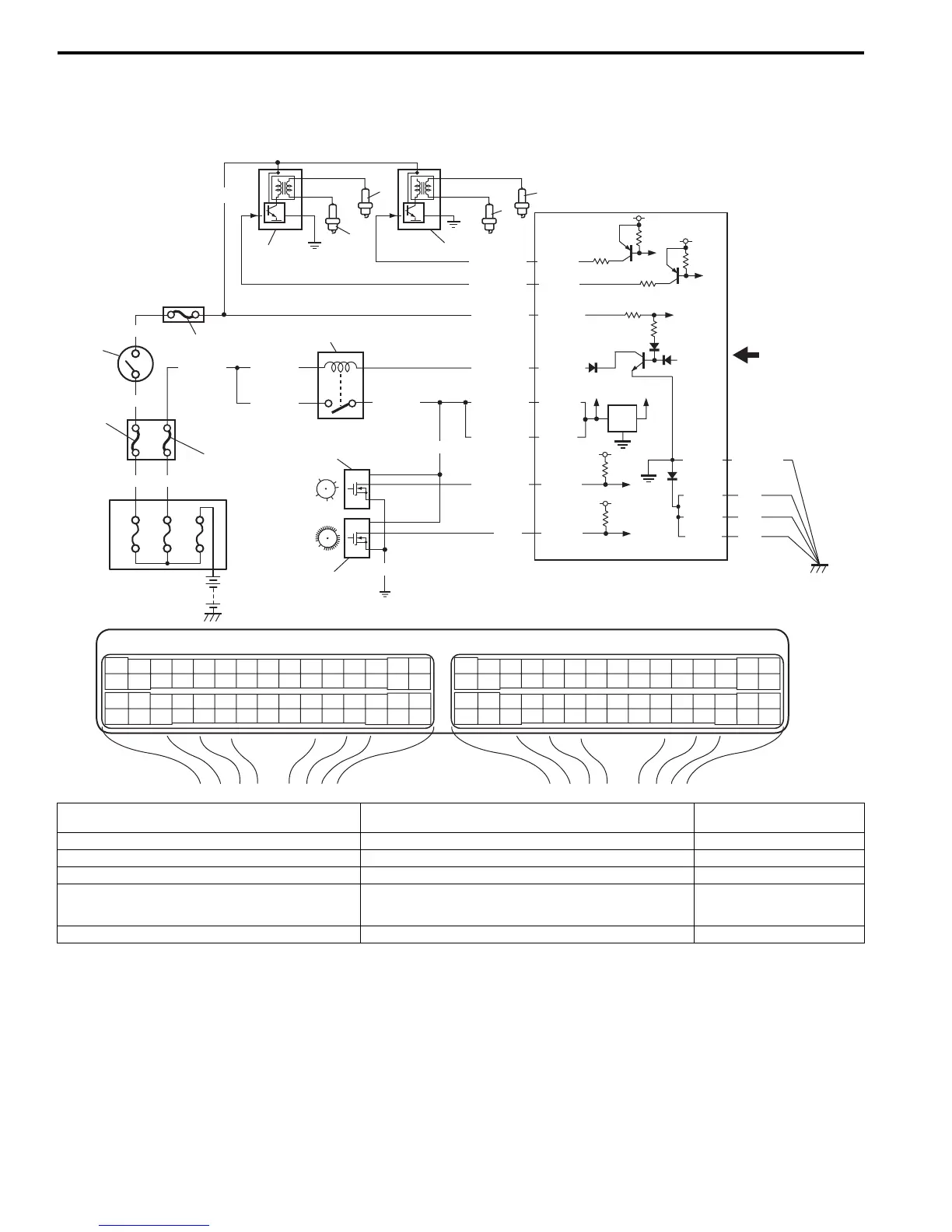
Ignition System Wiring Circuit Diagram
S7RS0B1802001
E23-60
E23-29
12V
5V
5V
E23-1
E23-16
BLK/WHT
BLK/RED
BLK/RED
BLK/RED
BLK/YEL BLK/YEL
BLK/YEL
GRN
BLKWHT
WHT
BRN/WHT
BLK/ORN
BLK
BLK
C37-20
BLK/RED
PNK
5V
C37-21
BLK/WHT
7
3
4
1
12
5
6
2
11
8
9
10
GRN/YEL
GRN/WHT
C37-6
C37-5
5V
5V
RED/YEL
C37-58
C37-15
C37-30
E23 C37
34
1819
5671011
1720
47 46495051
2122
52
1625
9
24
14
29
5557 54 53
59
60 58
2
262728
15
30
56 48
32 31343536374042 39 38
44
45 43 41 33
11213
23
834
1819
5671011
1720
47 46495051
2122
52
1625
9
24
14
29
5557 54 53
59
60 58
2
262728
15
30
56 48
32 31343536374042 39 38
44
45 43 41 33
11213
23
8
13
14
15
16
17
50A 50A 80A
BLK/ORN
E23-31
BLK
I4RS0B180001-01
1. Ignition switch 7. No.1 spark plug 13. Individual circuit fuse box
No.1
2. Main relay 8. No.2 spark plug 14. “IG ACC” fuse
3. Ignition coil assembly for No.1 and No.4 spark plugs 9. No.3 spark plug 15. “FI” fuse
4. Ignition coil assembly for No.2 and No.3 spark plugs 10. No.4 spark plug 16. Junction block assembly
5. CMP sensor 11. Sensed information (MAP sensor, ECT sensor, MAF and IAT
sensor, TP sensor, Knock sensor, VSS, Electric load signal,
Engine start signal)
17. “IG COIL” fuse
6. CKP sensor 12. Battery fuse box
 Loading...


