Engine General Information and Diagnosis: 1A-21
Component Location
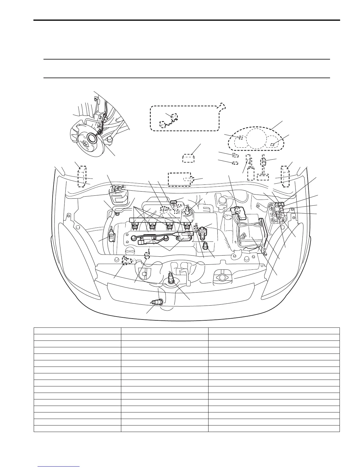
Electronic Control System Components Location
S7RS0B1103001
NOTE
The figure shows left-hand steering vehicle. For right-hand steering vehicle, parts with (*) are installed
at the opposite side.
I*
E*
G*
D
K
H*
J
C*
7
A
F
c
L
i
m
f
B*
e
g
k
l
13
3*
4
j
10
12
h
5
8
a
9
b
1
5-1
d
2
11
6
14*
I7RS0B110011-02
Information sensors Control devices Others
1. MAF and IAT sensor a: Fuel injector A: ECM
2. TP sensor b: EVAP canister purge valve B: Combination meter
3. Brake light switch c: Fuel pump relay C: EVAP canister
4. ECT sensor d: EGR valve D: A/C evaporator outlet air temp. sensor (manual A/C model)
5. HO2S-1 e: MIL E: Data link connector
5-1. HO2S-2 f: Radiator cooling fan relay No.3 F: A/C compressor relay
6. Wheel speed sensor (VSS) g: Immobilizer indicator light G: TCM (A/T model)
7. Battery h: Ignition coil assembly (with ignitor) H: BCM (included in junction block assembly)
8. CMP sensor i: Main relay I: Immobilizer coil antenna
9. MAP sensor j: Oil control valve J: EPS control module
10. CKP sensor k: Radiator cooling fan relay No.2 K: A/C refrigerant pressure sensor
11. Fuel level sensor l: Radiator cooling fan relay No.1 L: Diagnosis connector (Hong Kong model)
12. Knock sensor m: Starting motor control relay
13. Electric load current sensor
14. APP sensor
 Loading...


