Fuel System: 1G-2
Fuel Pump Description
S7RS0B1701003
The fuel pump (1) is an in-tank type electric pump.
Incorporated in the pump assembly are;
a fuel filter (2) and a fuel pressure regulator (3) are
included and a fuel level gauge (4) is attached.
Addition of the fuel pressure regulator to the fuel pump
makes it possible to maintain the fuel pressure at
constant level and ECM controls compensation for
variation in the intake manifold pressure.
Schematic and Routing Diagram
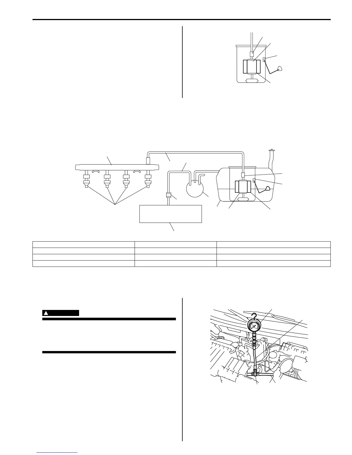
Fuel Delivery System Diagram
S7RS0B1702001
Diagnostic Information and Procedures
Fuel Pressure Inspection
S7RS0B1704001
WARNING
!
Before starting the following procedure, be
sure to observe “Precautions on Fuel System
Service” in order to reduce the risk or fire
and personal injury.
1) Relieve fuel pressure in fuel feed line referring to
“Fuel Pressure Relief Procedure”.
2) Disconnect fuel feed hose from fuel delivery pipe.
3) Connect special tools and hose between fuel feed
hose (1) and fuel delivery pipe as shown in figure,
and clamp hoses securely in order to ensure that no
leaks occur during checking.
Special tool
(A): 09912–58442
(B): 09912–58432
(C): 09912–58490
1
3
2
4
I6RS0C170001-01
4
6
7
8
12
2
3
11
10
5
1
9
I6RS0C170002-01
1. Fuel tank 5. Fuel injector 9. EVAP canister
2. Fuel pump 6. Fuel feed line 10. Fuel filter
3. Fuel pressure regulator 7. Fuel vapor line 11. Main fuel level sensor
4. Delivery pipe 8. Intake manifold 12. EVAP canister purge valve
1
(C)
(B)
(A)
I3RM0A170004-01
 Loading...


