8B-116 Air Bag System:
• For passenger air bag (inflator) module
a. Clear space (3) on ground about 185 cm (6 ft)
in diameter where passenger air bag (inflator)
module (1) is set for deployment. Paved,
outdoor location where there is no activity is
preferred. If outdoor location is not available,
use space on shop floor where there is no
activity and sufficient ventilation is provided.
Ensure no loose or flammable object exists
within deployment area.
b. Place deployment fixture (A) on ground in step
a.
Special tool
(A): 09932-75041
c. Fill plastic reservoir in deployment fixture (A)
with water or sand. This is necessary to
provide sufficient stabilization of fixture during
deployment.
d. Attach passenger air bag (inflator) module (1)
in deployment fixture (A) securely using M8
bolt (2).
CAUTION
!
Be sure to use M8 size and 7T strength bolt
for fixing passenger air bag (inflator) module
(1) to deployment fixture (A).
• For side-air bag (inflator) module
a. Remove sleeve (1) and sleeve lock nut (2), if
equipped.
b. Clear space (3) on ground about 185 cm (6 ft)
in diameter where side-air bag (inflator)
module for deployment. Paved, outdoor
location where there is no activity is preferred.
If outdoor location is not available, space on
shop floor where there is no activity and
provide sufficient ventilation. Ensure no loose
or flammable objects are within deployment
area.
c. Place deployment fixture (A) on ground.
Special tool
(A): 09932–75041
d. Fill plastic reservoir in deployment fixture (A)
with water or sand. This is necessary to
provide sufficient stabilization of fixture during
deployment.
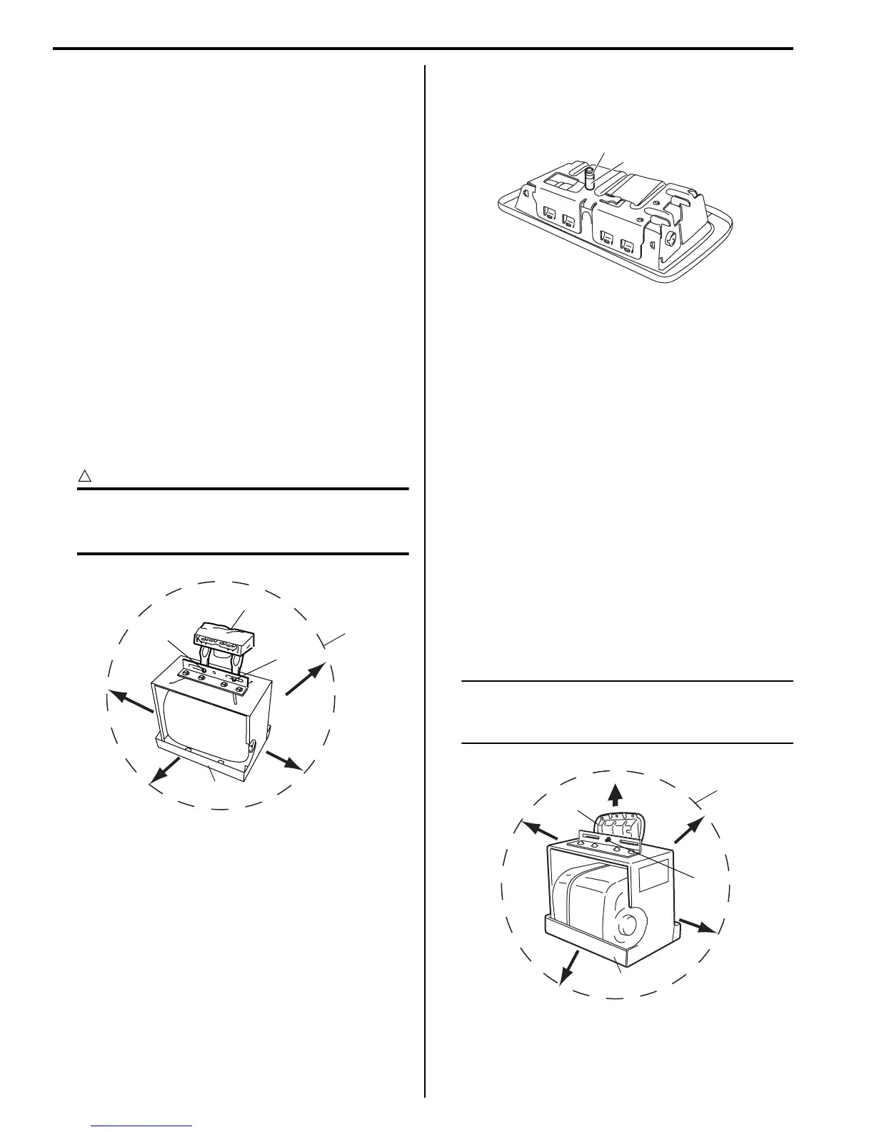
e. Attach side-air bag (inflator) module (1) in
deployment fixture using mounting
attachment, sleeve lock nut and washer (2).
NOTE
Make sure that deploying direction faces as
shown in figure against mounting
attachment.
1
(A)
2
2
3
I4RS0A820087-01
2
1
I4RS0A820088-01
1
(A)
2
3
I4RS0A820089-01
 Loading...


