Engine General Information and Diagnosis: 1A-75
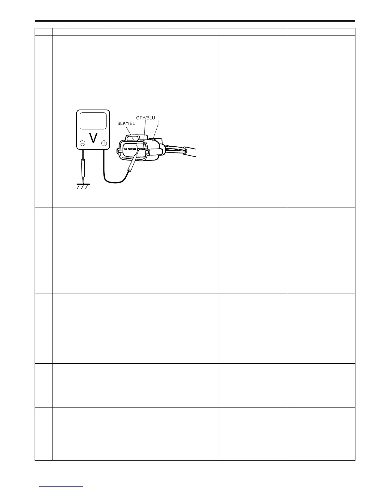
3 IAT sensor voltage check
1) Disconnect connector from MAF and IAT sensor with
ignition switch turned OFF.
2) Check for proper connection to MAF and IAT sensor at
“BLK/YEL” and “GRY/BLU” wire terminals.
3) If OK, then turn ON ignition switch, measure voltage
between “BLK/YEL” wire terminal of MAF and IAT
sensor connector (1) and vehicle body ground.
Is voltage about 4 – 6 V?
Go to Step 7. Go to Step 4.
4 ECM voltage check
1) Turn OFF ignition switch.
2) Remove ECM from its bracket with ECM connectors
connected.
3) Check for proper connection of ECM connector at “C37-
25” terminal.
4) If OK, then turn ON ignition switch, measure voltage
between “C37-25” terminal of ECM connector and
vehicle body ground.
Is voltage about 4 – 6 V?
“BLK/YEL” wire is open
circuit. If wire and
connection are OK, go
to Step 5.
Go to Step 5.
5 Wire circuit check
1) Disconnect connectors from ECM with ignition switch
turned OFF.
2) Turn ON ignition switch.
3) Measure voltage between “BLK/YEL” wire terminal of
MAF and IAT sensor connector and vehicle body
ground.
Is voltage about 0 V?
Go to Step 6. “BLK/YEL” wire is
shorted to other circuit.
If wire is OK, substitute
a known-good ECM and
recheck.
6 Wire circuit check
1) Measure resistance between “C37-25” terminal of ECM
connector and “BLK/YEL” wire terminal of MAF and IAT
sensor connector with ignition switch turned OFF.
Is resistance below 5
Ω
?
Go to Step 7. “BLK/YEL” wire is high
resistance circuit.
7 Ground circuit check
1) Connect connectors to ECM.
2) Measure resistance between “GRY/BLU” wire terminal
of MAF and IAT sensor connector and vehicle body
ground with ignition switch turned OFF.
Is resistance below 5
Ω
?
Go to Step 9. Go to Step 8.
Step Action Yes No
I4RS0B110020-01
 Loading...


