1A-78 Engine General Information and Diagnosis:
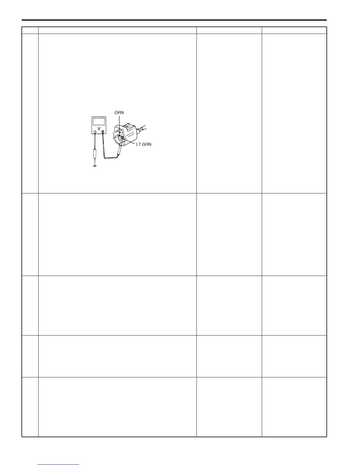
5 Wire harness check
1) Disconnect ECT sensor connector with ignition switch
turned OFF.
2) Check for proper connection to ECT sensor connector at
“ORN” and “LT GRN” wire terminals.
3) If OK, then with ignition switch ON, measure voltage
between “LT GRN” wire terminal of ECT sensor
connector and vehicle body ground.
Is measured voltage applied to “LT GRN” wire terminal about
4 – 6 V?
Go to Step 9. Go to Step 6.
6 ECM voltage check
1) Turn OFF ignition switch.
2) Remove ECM from its bracket with ECM connectors
connected.
3) Check for proper connection of ECM connector at “C37-
24” terminal.
4) If OK, then turn ON ignition switch, measure voltage
between “C37-24” terminal of ECM connector and
vehicle body ground.
Is voltage about 4 – 6 V?
“LT GRN” wire is open
circuit.
If wire and connection
are OK, go to Step 7.
Go to Step 7.
7 Wire circuit check
1) Disconnect connectors from ECM with ignition switch
turned OFF.
2) Turn ignition switch to ON position.
3) Measure voltage between “LT GRN” wire terminal of
ECT sensor connector and body ground.
Is voltage about 0 V?
Go to Step 8. “LT GRN” wire is
shorted to other circuit.
If wire is OK, substitute
a known-good ECM and
recheck.
8 Wire circuit check
1) Measure resistance between “C37-24” terminal of ECM
connector and “LT GRN” wire terminal of ECT sensor
connector with ignition switch turned OFF.
Is resistance below 5
Ω
?
Go to Step 9. “LT GRN” wire is high
resistance circuit.
9 Ground circuit check
1) Connect connectors to ECM.
2) Check for proper connection of ECT sensor connector at
“ORN” wire terminal.
3) Measure resistance between “ORN” wire terminal of
ECT sensor connector and vehicle body ground.
Is resistance below 5
Ω
?
Go to Step 11. Go to Step 10.
Step Action Yes No
I2RH01110067-01
 Loading...


