9C-5 Instrumentation / Driver Info. / Horn:
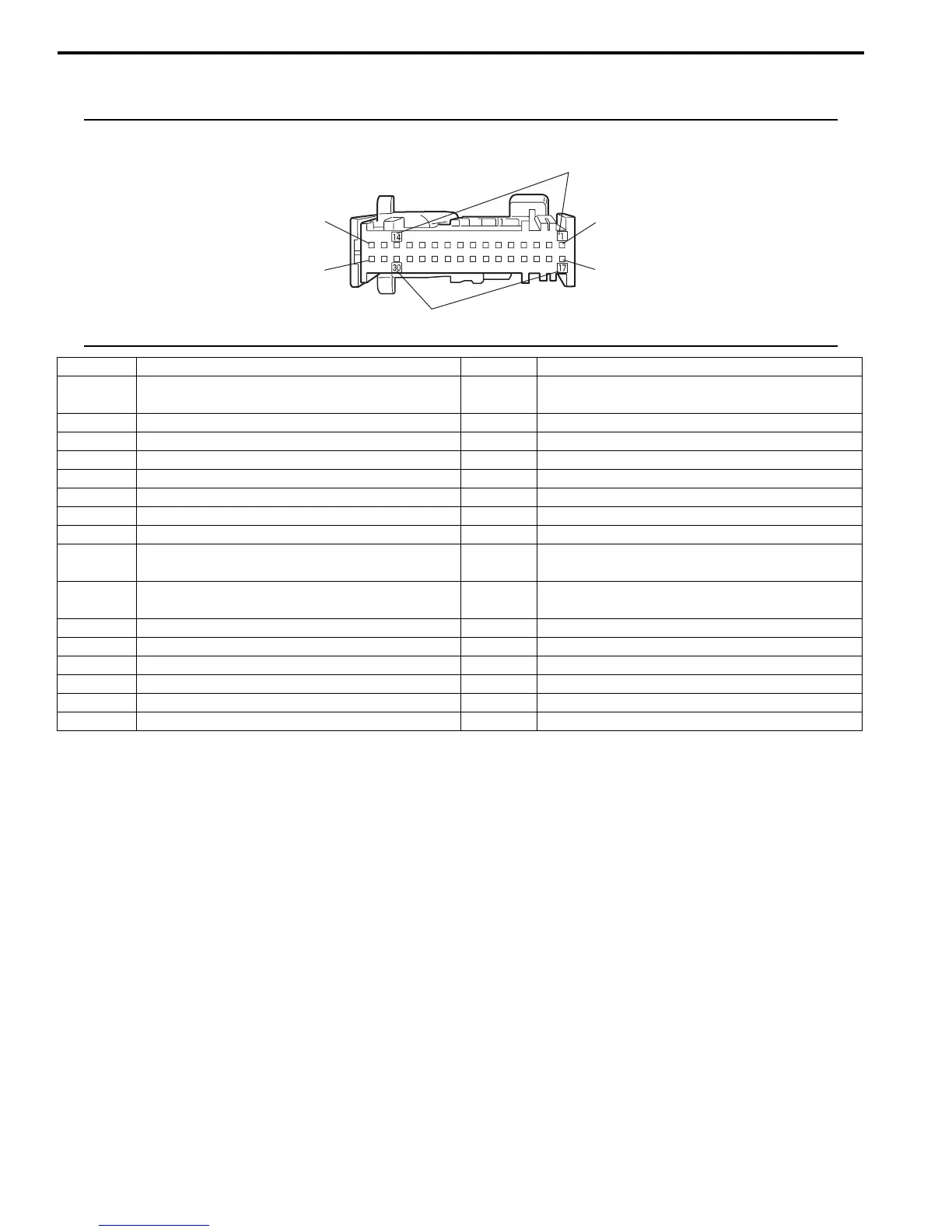
Terminal arrangement of coupler viewed from terminal side
NOTE
Molded numbers (1) have no relation to the terminal numbers.
Terminal Circuit Terminal Circuit
G28-1 To turn signal and hazard warning relay (turn
R)
G28-17 —
G28-2 — G28-18 —
G28-3 — G28-19 —
G28-4 — G28-20 —
G28-5 To SDM (air bag warning light control signal) G28-21 —
G28-6 — G28-22 To lighting switch (high beam)
G28-7 CAN communication line (Active High signal) G28-23 —
G28-8 CAN communication line (Active High signal) G28-24 —
G28-9 CAN communication line (Active Low signal) G28-25 To P/S control module (EPS warning light
control signal)
G28-10 CAN communication line (Active Low signal) G28-26 To turn signal and hazard warning relay (turn
L)
G28-11 — G28-27 —
G28-12 — G28-28 —
G28-13 — G28-29 Fuel level sensor ground
G28-14 — G28-30 To fuel level sensor
G28-15 — G28-31 To METER fuse
G28-16 GND G28-32 To RADIO fuse
G28-1
G28-16
G28-32
G28-17
1
1
I4RS0A930003-02
 Loading...


