1A-84 Engine General Information and Diagnosis:
DTC Troubleshooting
NOTE
• When measuring circuit voltage, resistance and/or pulse signal at ECM connector, connect the
special tool to ECM and/or the ECM connectors referring to “Inspection of ECM and Its Circuits”.
• Upon completion of inspection and repair work, perform “DTC Confirmation Procedure” and
confirm that the trouble has been corrected.
Step Action Yes No
1 Was “Engine and Emission Control System Check”
performed?
Go to Step 2. Go to “Engine and
Emission Control
System Check”.
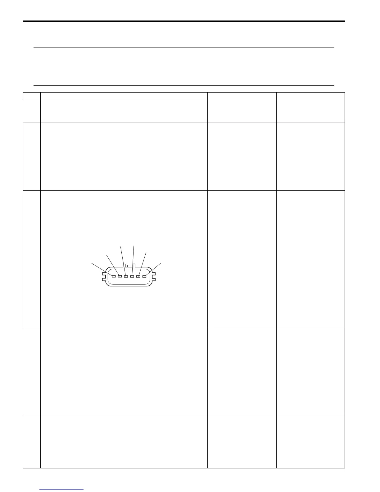
2 TP sensor and its circuit check
1) Connect scan tool to DLC with ignition switch turned
OFF.
2) Turn ON ignition switch, check “TP Sensor 1 Volt”
displayed on scan tool when accelerator pedal is idle
position and fully depressed.
Is displayed TP sensor value as described voltage in “Scan
Tool Data:”?
Intermittent trouble.
Check for intermittent
referring to “Intermittent
and Poor Connection
Inspection in Section
00”.
Go to Step 3.
3 ECM voltage check
1) Disconnect connector from electric throttle body with
ignition switch turned OFF.
2) Check for proper connection to electric throttle body at
“RED”, “GRN” and “BLK” wire terminals.
3) If OK, measure voltage between “RED” wire terminal of
electric throttle body connector and engine ground with
ignition switch turned ON.
Is voltage 4 – 6 V?
Go to Step 6. Go to Step 4.
4 ECM voltage check
1) Turn OFF ignition switch.
2) Remove ECM from its bracket with ECM connectors
connected.
3) Check for proper connection of ECM connector at “C37-
43” terminal.
4) If OK, measure voltage between “C37-43” terminal of
ECM connector and engine ground with ignition switch
turned ON.
Is voltage 4 – 6 V?
“RED” wire is open or
high resistance circuit.
Go to Step 5.
5 Wire harness check
1) Disconnect connectors from ECM with ignition switch
turned OFF.
2) Measure resistance between “C37-43” terminal of ECM
connector and engine ground.
Is resistance infinity?
Substitute a known-
good ECM and check.
“RED” wire is shorted to
ground circuit.
"GRN"
"RED"
"WHT"
"BLK"
"LT GRN/BLK"
"LT GRN/RED"
I4RS0B110022-02
 Loading...


