Body Electrical Control System: 10B-22
ESP® model
DTC Detecting Condition and Trouble Area
DTC Confirmation Procedure
1) Connect scan tool to DLC with ignition switch turned OFF.
2) Turn ON ignition switch and clear DTC by using scan tool.
3) Start engine and run it for 1 min. or more.
4) Check DTC.
[F]
E85
16
1
15
2
3
4
5
6
7
8
9
10
11
12
13
14
17
18
19
20
21
22
23
24
25
26
27
28
29
30
31
32
33
34
35
36
37
38
39
40
41
42
43
44
45
46
47
[D]
1234567891011141516
36 34 33 32 31 30 29 24 2337
181920
G49
[A]
E23 C37
34
1819
5671011
17
20
47 46
495051
2122
52
16
25
9
24
14
29
5557 54 53
59
60
58
2
262728
15
30
56
48
32 31
343536374042 39 38
44
45
43 41 33
1
1213
23
8
34
1819
5671011
17
20
47 46
495051
2122
52
16
25
9
24
14
29
5557 54 53
59
60 58
2
262728
15
30
56
48
32 31
343536374042 39 38
44
45
43 41 33
1
1213
23
8
[C]
G28
1234567
8
910111213141516
1718
19
20
212223242526272829303132
[E]
G54
109 321
[B]
G37
E46
1234567
1234567
891011
891011121314 1213141516171819202122
4
6
1
2
3
RED
WHT
RED
WHT
RED
WHT
RED
WHT
E23-3
E23-18
E85-42
E85-46
E85-13
E85-44
G37-4
G37-2
RED
WHT
RED
WHT
G49-19
G49-18
5
7
WHTG54-9
REDG54-10
G28-8
G28-10
G28-7 RED
G28-9 WHT
RED/BLK
WHT/BLK
RED
WHT
E46-1
E46-2
G37-1
G37-3
+BB
8
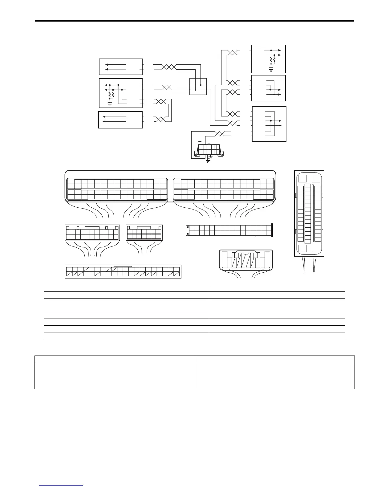
I7RS0BA20005-01
[A]: ECM connector (viewed from harness side) 1. ECM
[B]: BCM connector (viewed from harness side) 2. ESP® control module
[C]: Combination meter connector (viewed from harness side) 3. BCM
[D]: Keyless start control module connector (viewed from harness side) 4. Steering angle sensor
[E]: Steering angle sensor connector (viewed from harness side) 5. Combination meter
[F]: ESP® control module connector (viewed from terminal side) 6. Keyless start control module
7. CAN junction connector
8. Data link connector (DLC)
DTC detecting condition Trouble area
BCM can not receive CAN data from combination meter
for longer than specified time continuously.
• CAN communication circuit
•BCM
• Combination meter
 Loading...


