10C-17 Immobilizer Control System:
Reference Waveform NOTE
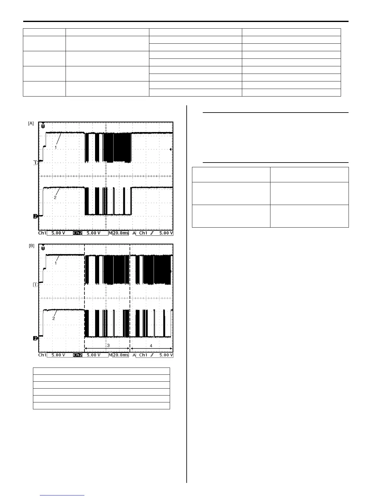
When ECM cannot read the transponder code
at the first try, ECM tries to read the
transponder code repeatedly up to 8 times.
The second waveform is the example
showing that ECM read the transponder code
successfully at the second try.
Terminal Circuit Normal Voltage Condition
G24-1 Power supply
About 12.0 V Ignition switch at ON position
0.0 V Ignition switch at OFF position
G24-2 Ground
0.0 V Ignition switch at ON position
0.0 V Ignition switch at OFF position
G24-3 Serial communication line
See the reference waveform. —
0.0 V Ignition switch at OFF position
G24-4 Clock line
See the reference waveform. —
0.0 V Ignition switch at OFF position
[A]: The transponder code read successfully at the first try.
[B]: The transponder code read successfully at the second try.
1. Serial communication line
2. Clock line
3. First try
4. Second try
I4RS0AA30007-01
Measurement terminals CH1: G24-3 to G24-2
CH2: G24-4 to G24-2
Oscilloscope settings CH1: 5 V/DIV
CH2: 5 V/DIV
TIME: 20 ms
Measurement condition Right after the ignition
switch is turned ON, the
waveform can be read.
 Loading...


