1A-108 Engine General Information and Diagnosis:
DTC Troubleshooting
NOTE
• When measuring circuit voltage, resistance and/or pulse signal at ECM connector, connect the
special tool to ECM and/or the ECM connectors referring to “Inspection of ECM and Its Circuits”.
• Upon completion of inspection and repair work, perform “DTC Confirmation Procedure” and
confirm that the trouble has been corrected.
Step Action Yes No
1 Was “Engine and Emission Control System Check”
performed?
Go to Step 2. Go to “Engine and
Emission Control
System Check”.
2 Knock sensor circuit check
1) Remove ECM from its bracket with ECM connectors
connected.
2) Measure voltage between “C37-56” terminal of ECM
connector and vehicle body ground with engine running.
Is voltage within 1.23 – 3.91 V?
Intermittent trouble.
Check for intermittent
referring to “Intermittent
and Poor Connection
Inspection in Section
00”. If OK, substitute a
known-good ECM and
recheck.
Go to Step 3.
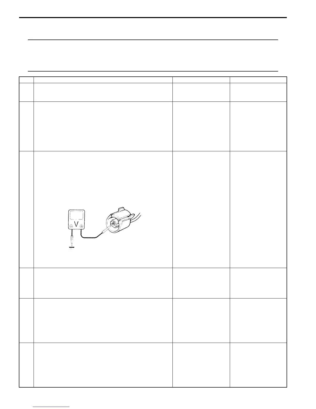
3 Knock sensor circuit for open check
1) Disconnect connector from knock sensor with ignition
switch turned OFF.
2) Turn ON ignition switch, measure voltage between
“RED” wire of knock sensor connector and engine
ground.
Is voltage 4 – 6 V?
Go to Step 6. Go to Step 4.
4 Knock sensor circuit for open check
1) Turn ON ignition switch, measure voltage between “C37-
56” terminal of ECM connector and engine ground
Is voltage 4 – 6 V?
“RED” wire is open
circuit.
Go to Step 5.
5 Knock sensor circuit for short check
1) Disconnect connectors from ECM with ignition switch
turned OFF.
2) Measure resistance between “C37-56” terminal of ECM
connector and vehicle body ground.
Is resistance infinity?
Go to Step 6. “RED” wire is shorted to
ground circuit.
If wire is OK, substitute
a known-good ECM and
recheck.
6 Knock sensor circuit for short check
1) Disconnect connectors from ECM with ignition switch
turned OFF.
2) Turn ON ignition switch, measure voltage between “C37-
56” terminal of ECM connector and vehicle body ground.
Is voltage 0 V?
Go to Step 7. “RED” wire is shorted to
other circuit.
I2RH01110089-01
 Loading...


