Engine General Information and Diagnosis: 1A-119
DTC Troubleshooting
NOTE
• When measuring circuit voltage, resistance and/or pulse signal at ECM connector, connect the
special tool to ECM and/or the ECM connectors referring to “Inspection of ECM and Its Circuits”.
• Upon completion of inspection and repair work, perform “DTC Confirmation Procedure” and
confirm that the trouble has been corrected.
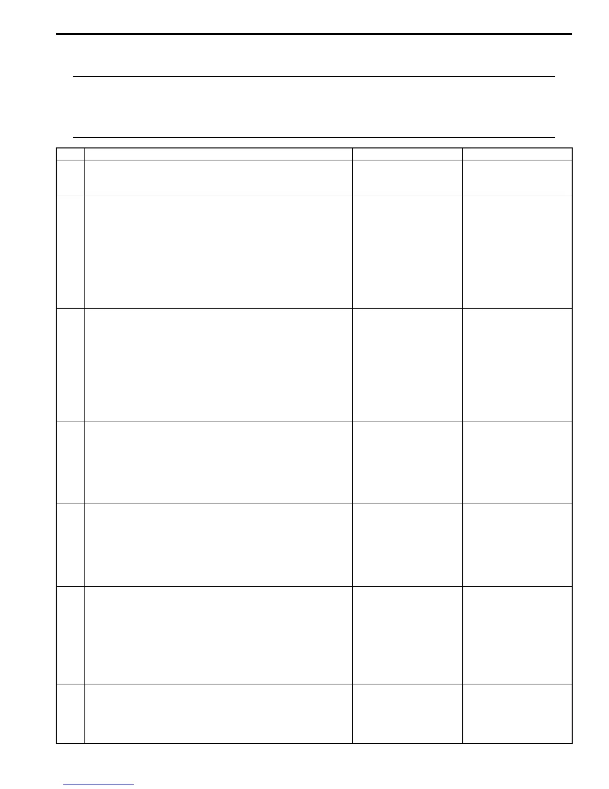
Step Action Yes No
1 Was “Engine and Emission Control System Check”
performed?
Go to Step 2. Go to “Engine and
Emission Control
System Description”.
2 EGR valve power supply circuit check
1) Remove air intake pipe.
2) With ignition switch turned OFF, disconnect EGR valve
connector.
3) With ignition switch turned ON, measure voltage
between “BLK/RED” wire terminal of EGR valve
connector and vehicle body ground.
Is check voltage 10 – 14 V?
Go to Step 3. “BLK/RED” wire is open
circuit.
3 Wire circuit check
1) Disconnect connectors from ECM with ignition switch
turned OFF.
2) Turn ON ignition switch.
3) Measure voltage between engine ground and each
“GRN/RED”, “GRN/ORN”, “WHT/RED”, “BRN/YEL” wire
terminals of EGR valve connector.
Is each voltage 0 V?
Go to Step 4. Faulty wire(s) are
shorted to other circuit.
If wires are OK,
substitute a known-
good ECM and recheck.
4 Wire circuit check
1) With ignition switch turned OFF, measure resistance
between engine ground and each “GRN/RED”, “GRN/
ORN”, “WHT/RED”, “BRN/YEL” wire terminals of EGR
valve connector.
Is resistance infinity?
Go to Step 5. Faulty wire(s) are
shorted to ground
circuit.
If wires are OK,
substitute a known-
good ECM and recheck.
5 Short circuit check for EGR valve control circuit
1) With ignition turned OFF, measure resistance between
each EGR valve control circuit wire (“GRN/RED”, “GRN/
ORN”, “WHT/RED” and “BRN/YEL” wire) and each EGR
valve control circuit wire.
Is each resistance infinity?
Go to Step 6. Faulty wire(s) are short
circuit.
6 EGR valve stepper motor coil circuit check
1) With ignition switch turned OFF, connect EGR valve
connector.
2) Measure resistance between “E23-1/16” and each “C37-
4”, “C37-3”, “C37-19”, “C37-18” terminals of ECM
connector.
Is each resistance 20 – 31
Ω
at 20
°
C, 68
°
F?
Faulty ECM. Substitute
a known-good ECM and
recheck.
Go to Step 7.
7 EGR valve check
1) Check EGR valve resistance referring to “EGR Valve
Inspection in Section 1B”.
Is resistance within specified value?
Faulty wire(s) are open
or high resistance
circuit. If wires are OK,
substitute a known-
good ECM and recheck.
Faulty EGR valve.
 Loading...


