1A-126 Engine General Information and Diagnosis:
3 Wire circuit check
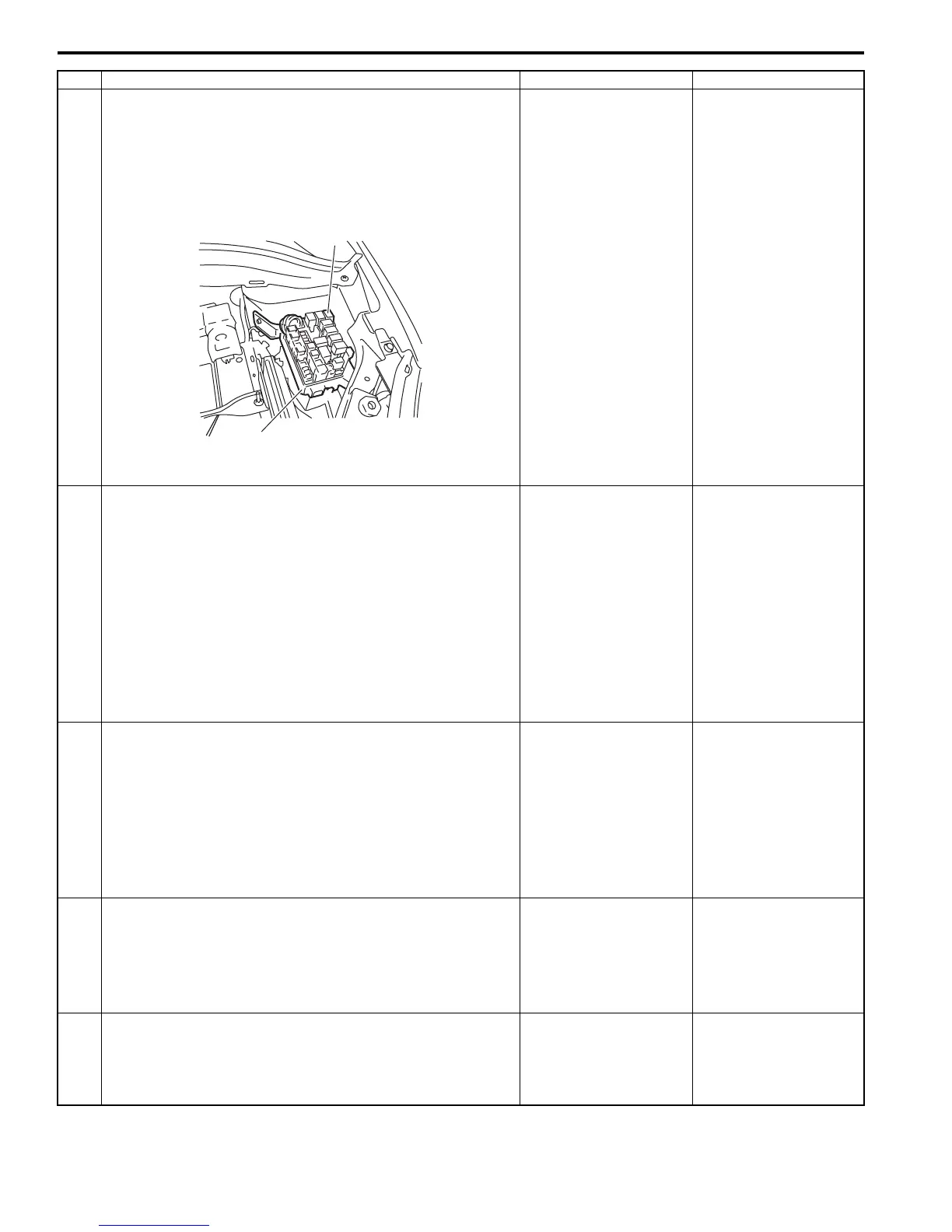
1) Disconnect radiator cooling fan relay No. 1 (1) from
individual circuit fuse box No.1 (2) with ignition switch
turned OFF.
2) Turn ON ignition switch, measure voltage between each
engine ground to “BLK/RED” and “GRY” wire terminal.
Is voltage 10 – 14 V?
Go to Step 4. Open wire in “BLK/RED”
and/or “GRY” wire are
open circuit.
4 Wire circuit check
1) Connect radiator cooling fan relay No. 1 to individual
circuit fuse box No.1 with ignition switch turned OFF.
2) Remove ECM from its bracket with ECM connectors
connected.
3) Turn ON ignition switch, make sure that A/C switch is
OFF position.
4) Measure voltage between vehicle body ground and
“E23-46” terminal of ECM connector when engine
coolant temp. is below 95 °C, 203 °F.
Is voltage 10 – 14 V?
Go to Step 8. Go to Step 5.
5 Wire circuit check
1) Disconnect connectors from ECM with ignition switch
turned OFF.
2) Disconnect radiator cooling fan relay No. 1 from
individual circuit fuse box No.1.
3) Measure resistance between “E23-46” terminal of ECM
connector and vehicle ground.
Is resistance infinity?
Go to Step 6. “LT GRN” wire is
shorted to ground
circuit.
6 Wire circuit check
1) Turn ON ignition switch.
2) Measure voltage between “E23-46” terminal of ECM
connector and vehicle body ground.
Is voltage 0 V?
Go to Step 7. “LT GRN” wire is
shorted to other circuit.
7 Radiator cooling fan relay No. 1 check
1) Check radiator cooling fan relay No. 1 referring to
“Radiator Cooling Fan Relay Inspection in Section 1F”.
Is check result satisfactory?
“LT GRN” wire is open
circuit.
Replace relay.
Step Action Yes No
1
2
I7RS0A110010-01
 Loading...


