Engine General Information and Diagnosis: 1A-201
Troubleshooting
NOTE
When measuring circuit voltage, resistance and/or pulse signal at ECM connector, connect the special
tool to ECM and/or the ECM connectors referring to “Inspection of ECM and Its Circuits”.
Step Action Yes No
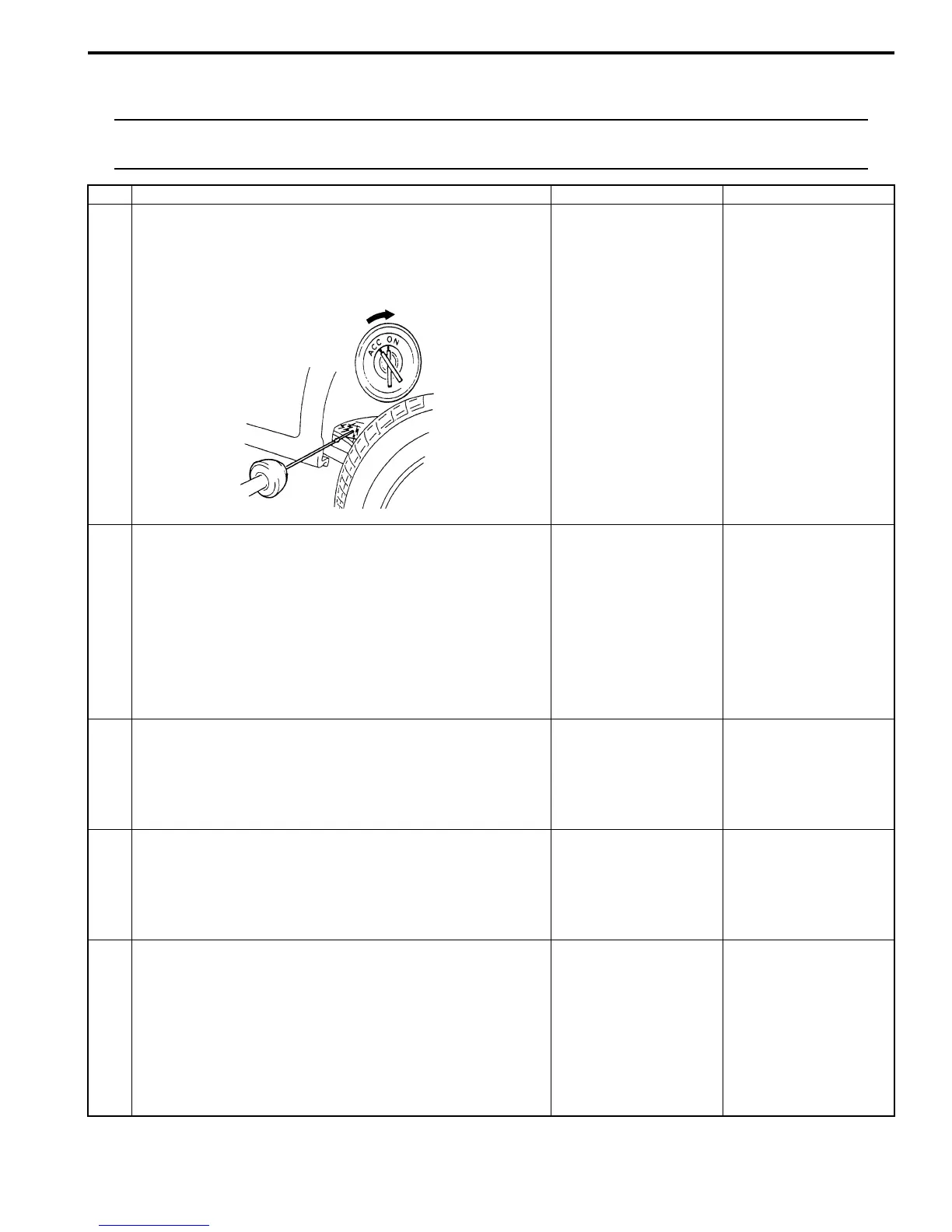
1 Fuel pump control system check for operation
Is fuel pump heard to operate 2 sec. after ignition switch is
turned ON?
Fuel pump circuit is in
good condition.
Go to Step 2.
2 Fuel pump relay power supply check
1) Disconnect fuel pump relay from individual circuit fuse
box No.1 with ignition switch turned OFF.
2) Check for proper connection to fuel pump relay at each
terminal.
3) If OK, turn ON ignition switch, measure voltage between
“BLK/WHT” wire terminal of fuel pump relay connector
and engine ground.
Is voltage 10 – 14 V?
Go to Step 3. “BLK/WHT” wire is open
or shorted to ground
circuit.
3 Fuel pump relay power supply check
1) Turn ON ignition switch, measure voltage between “BLK/
RED” wire terminal of fuel pump relay connector and
engine ground.
Is voltage 10 – 14 V?
Go to Step 4. “BLK/RED” wire is open
circuit.
4 Fuel pump relay check
1) Check fuel pump relay referring to “Main Relay, Fuel
Pump Relay and Starting Motor Control Relay Inspection
in Section 1C”.
Is relay in good condition?
Go to Step 5. Faulty relay.
5 Fuel pump relay drive signal check
1) Connect fuel pump relay to individual circuit fuse box
No.1.
2) Connect voltmeter between “E23-15” terminal of ECM
connector and vehicle body ground.
3) Measure voltage 2 second after ignition switch is turned
ON.
Is voltage 10 – 14 V?
Go to Step 6. “GRN/WHT” wire is
open circuit or shorted
to ground circuit.
I2RH01110132-01
 Loading...


