1D-51 Engine Mechanical:
Connecting Rod Bearing Clearance
1) Before checking bearing clearance, clean bearing
and crank pin.
2) Install bearing in connecting rod and bearing cap.
3) Place a piece of gauging plastic (1) to full width of
crank pin as contacted by bearing (parallel to
crankshaft), avoiding oil hole.
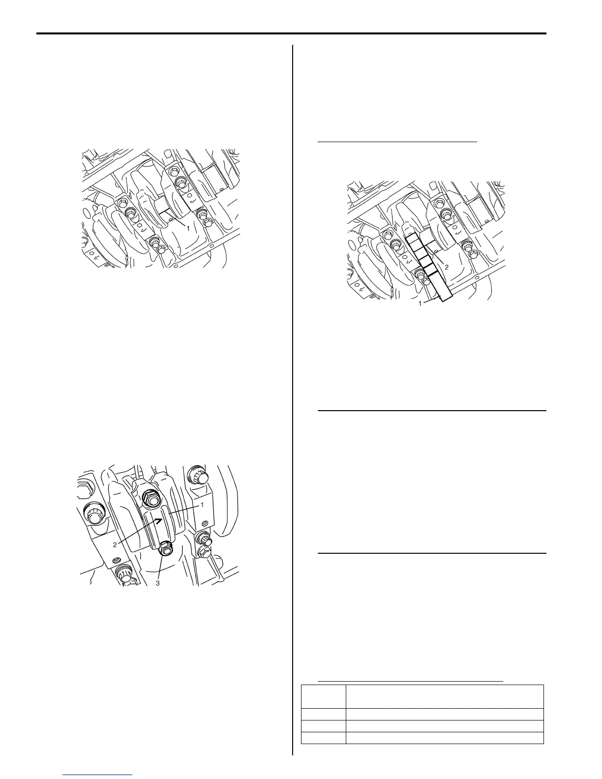
4) Install rod bearing cap (1) to connecting rod.
When installing cap, be sure to point arrow mark (2)
on cap to crankshaft pulley side, as shown in figure.
After applying engine oil to bearing cap bolts (3),
tighten bearing cap bolts (3) gradually as follows.
a) Tighten all bearing cap bolts to 15 N⋅m (1.5 kgf-
m, 11.0 lb-ft)
b) Retighten them to 45°
c) Repeat Step b) once again.
Tightening torque
Connecting rod bearing cap bolt: 15 N⋅m (1.5
kgf-m, 11.0 lb-ft) and then retighten by
turning through 45° twice
5) Remove cap and using a scale (1) on gauging
plastic envelope (2), measure gauging plastic (2)
width at the widest point (clearance).
If clearance exceed its limit, use a new standard size
bearing referring to “Selection of Connecting Rod
Bearings: ”.
After selecting new bearing, recheck clearance.
Connecting rod bearing clearance
Standard: 0.029 – 0.047 mm (0.0011 – 0.0018 in.)
Limit: 0.065 mm (0.0026 in.)
6) If clearance can not be brought to its limit even by
using a new standard size bearing, use next thicker
bearing and recheck clearance or regrind crank pin
to undersize and use 0.25 mm undersize bearing.
Selection of Connecting Rod Bearings
NOTE
• If bearing is in malcondition, or bearing
clearance is out of specification, select a
new standard bearing according to the
following procedure and install it.
• When replacing crankshaft or connecting
rod and its bearing due to any reason,
select new standard bearings to be
installed by referring to numbers stamped
on connecting rod and its cap and/or
alphabets stamped on crank web of No.3
cylinder.
1) Check stamped numbers on connecting rod and its
cap as shown.
Three kinds of numbers (“1”, “2” and “3”) represent
the following connecting rod big end inside
diameters.
For example, stamped number “1” indicates that
corresponding connecting rod big end inside
diameter is 45.000 – 45.006 mm (1.7717 – 1.7718
in.).
Connecting rod big end inside diameter
I2RH0B140121-01
I6RS0B141026-01
Stamped
numbers
Connecting rod big end inside diameter
1 45.0000 – 45.0060 mm (1.7717 – 1.7718 in.)
2 45.0061 – 45.0120 mm (1.7719 – 1.7721 in.)
3 45.0121 – 45.0180 mm (1.7722 – 1.7723 in.)
I2RH0B140123-01
 Loading...


