Front Suspension: 2B-16
4) Hoist vehicle and remove both wheels referring to
“Wheel Removal and Installation in Section 2D”.
5) Remove cotter pins and tie-rod end nuts, and then
disconnect both tie-rod ends from steering knuckles
referring to “Tie-Rod End Removal and Installation in
Section 6C”.
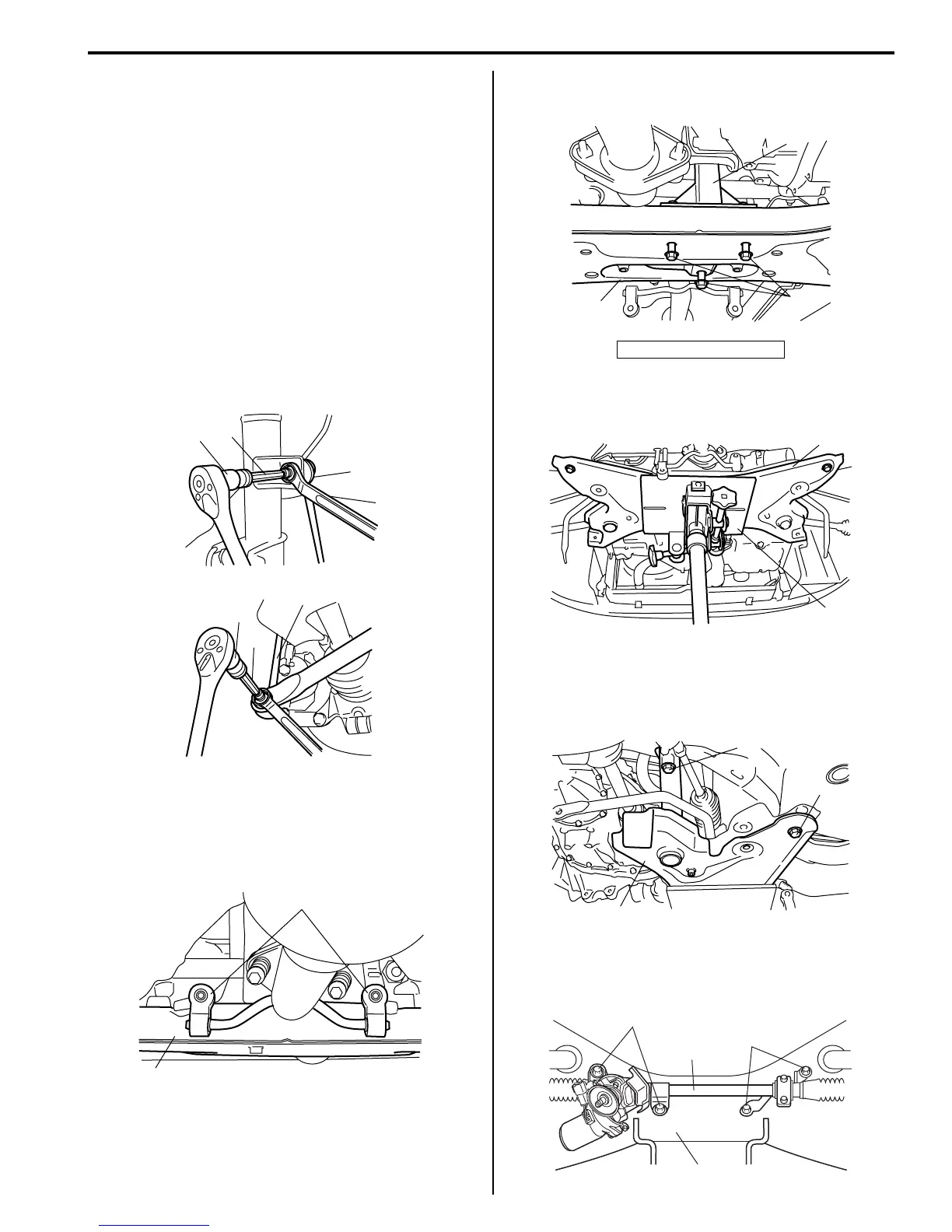
6) Disconnect couplers of torque sensor and P/S motor.
7) Remove suspension control arm referring to
“Suspension Control Arm / Bushing Removal and
Installation”.
8) Remove stabilizer joints (1).
When loosening joint nut, hold stud with special
tools.
Special tool
(A): 09900–00411 socket
(B): 09900–00413 5 mm
9) Support engine assemble by using supporting
device referring to “Engine Supporting Points in
Section 0A”.
10) Disconnect muffler No.1 mounting (1) from
suspension frame (2).
11) Remove engine rear mounting bolts (1) from engine
rear mounting (2).
12) Support front suspension frame (2) by using mission
jack (1).
13) Remove front suspension frame mounting bolts (1),
and then lower mission jack and remove front
suspension frame (2) with stabilizer bar and steering
gear case.
14) Remove steering gear case mounting No.1 bolts (1)
and No.2 bolts (2), then remove gear case (3) from
front suspension frame (4).
1
1
(A)
(A)
(B)
(B)
I4RS0A220038-01
1
2
I4RS0A220040-01
3. Suspension frame
2
3
1
I4RS0A220041-01
2
1
I4RS0A220042-01
1
2
1
I4RS0A220043-01
1
3
4
2
I4RS0B220010-02
 Loading...


